Functional Description
This guide describes how to setup the XPort EDGE evaluation kit and provides the information needed to evaluate the included XPort EDGE embedded Ethernet gateway. The intended audience is the engineers that design the XPort EDGE into their products.
Evaluation Kit Contents
Lantronix offers an XPort EDGE evaluation kit to provide a simple, quick, and cost-effective way to evaluate the XPort EDGE embedded Ethernet gateway. Use the development kit to integrate the XPort EDGE module to your product design and give your newly networked product a test drive.
- XPort EDGE embedded Ethernet gateway
- XPort EDGE evaluation board with socket for the XPort EDGE device server
- 5V DC power supply adapter (with international plugs)
- RS-232 null cable, DB9M/F
- CAT5e UTP RJ45M/M Ethernet cable
- Serial adapter, 25-pin to 9-pin
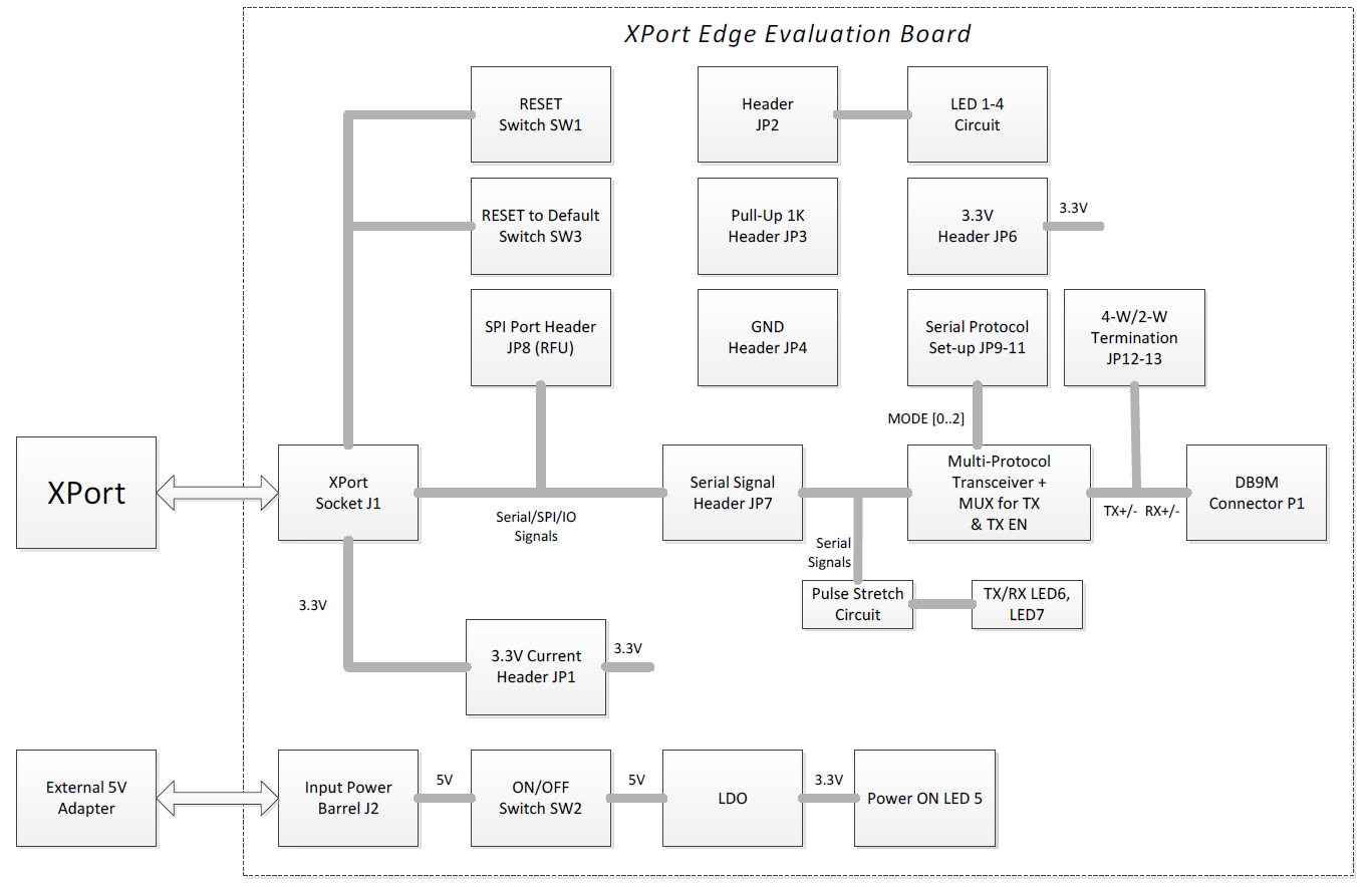
Evaluation Board Block Diagram
XPort EDGE Evaluation Board Block Diagram
XPort EDGE Evaluation Board Component Layout

Connectors, Headers and Switches
| Ref Des. | Connector/Header Functions |
|---|---|
| GND1 | System Ground Post |
| GND2 | Chassis Ground Post – connected to metal shells of XPort EDGE and DB9M |
| J1 | XPort EDGE Unit location |
| J2 | +5V DC from Wall Adaptor Power Input Barrel |
| JP1 | +3.3V Power Input Header to the XPort EDGE unit |
| JP2 | LED1 to LED4 Input Header |
| JP3 | General Purpose +3.3V Pull-Up 1 KOhm Header |
| JP4 | System Ground Header |
| JP5 | System Ground Header (not installed) |
| JP6 | +3.3V Header |
| JP7 | XPort EDGE Serial Connections to Multi-Protocol Transceiver Header |
| JP8 | Reserved for Future Use (RFU). Do not use. Leave open. |
| JP9 | MODE 0 – Multi-protocol Transceiver Setting Header |
| JP10 | MODE 1 – Multi-protocol Transceiver Setting Header |
| JP11 | MODE 2 – Multi-protocol Transceiver Setting Header |
| JP12 | Header to connect R38 = 120 Ohm termination across RX+/- in 4-wire/2-wire mode |
| JP13 | Header to connect R39 = 120 Ohm termination across TX+/- in 4-wire/2-wire mode |
| LED1 | General Purpose LED1 (Green). Input = JP2.1, logic high to turn LED on |
| LED2 | General Purpose LED2 (Yellow). Input = JP2.2, logic high to turn LED on |
| LED3 | General Purpose LED3 (Orange). Input = JP2.3, logic high to turn LED on |
| LED4 | General Purpose LED4 (Red). Input = JP2.4, logic high to turn LED on |
| LED5 | Power On Indicator (Blue) |
| LED6 | Serial TX Activity LED (Green) |
| LED7 | Serial RX Activity LED (Yellow) |
| P1 | DB9 male (DB9M) connector for Serial Port connection |
| SW1 | System Reset Switch |
| SW2 | +5VDC Power ON/OFF Switch for the whole board |
| SW3 | Reset to Default Switch |
| U1 | LDO to convert +5V to +3.3V to power the whole board |
| U2, U3 | Buffer circuit to drive Serial Activity LED6, LED7 |
| U4 | Exar SP336, Multi-protocol Transceiver |
| U5, U6 | Analog Switches to be used with Multi-Protocol Transceiver U4 |
Ethernet Interface
The evaluation board includes an RJ45 with magnetics built into the XPort EDGE unit making it ready to connect to Ethernet network.

Ethernet Interface Signals
| Signal Name | DIR | Contact | Primary Function |
|---|---|---|---|
| TX+ | Out | 1 | Differential Ethernet transmit data + |
| TX- | Out | 2 | Differential Ethernet transmit data - |
| RX+ | In | 3 | Differential Ethernet receive data + |
| RX- | In | 6 | Differential Ethernet receive data - |
| Not used | -- | 4 | Terminated |
| Not used | -- | 5 | Terminated |
| Not used | -- | 7 | Terminated |
| Not Used | -- | 8 | Terminated |
| SHIELD | -- | -- | Chassis ground |
XPort EDGE Pinout
The XPort EDGE unit connects to the J1- XPort EDGE socket on the evaluation board.
Note
See descriptions on SW3 for how to use Reset to Default#.
XPort EDGE Pinout Signals
| J1 Pin | Signal Names | Function |
|---|---|---|
| 1 | GND | System Ground |
| 2 | VCC | +3.3V Power Input |
| 3 | RESET_N | Reset Input, active low (3.3V signal) |
| 4 | TXDA | Serial Data Output (3.3V signal) |
| 5 | RXDA | Serial Data Input (3.3V signal) |
| 6 | RTSA | Serial Hardware Handshake Output, or CP1, or Reset to Default# (3.3V signal) |
| 7 | DTRA | Serial MODEM Input, or CP2, or Reset to Default# (3.3V signal) |
| 8 | CTSA | Serial Hardware Handshake Input, or CP3, or Reset to Default# (3.3V signal) |
Serial Interface
JP7 - XPort EDGE Serial Interface
- JP7 - odd pins are connected to serial transceiver circuits (U4, U5, and U6).
- JP7 - even pins are connected to XPort EDGE unit.
- To connect XPort EDGE unit to the serial transceiver circuit, install all jumpers as shown in picture to connect odd to even pins.
- No jumpers on JP7 pin 4, 6, 10 (i.e. no serial connections) if use pins 3, 5, 9 as CPx.
XPort EDGE Serial Interface Signals
| JP7 – Odd Pin |
Function on Serial Transceiver Circuit |
JP7 - Even Pin |
Role on XPort EDGE Unit (3.3V Signals) |
|---|---|---|---|
| 1 | Input | 2 | Serial Data Output TXDA |
| 3 | Input | 4 | Output RTSA, or CP1, or Reset to Default# |
| 5 | Input | 6 | Output DTRA, or CP2, or Reset to Default# |
| 7 | Output | 8 | Serial Data Input RXA |
| 9 | Output | 10 | Input CTSA, or CP3, or Reset to Default# |
| 11 | RFU Output | 12 | No Connection (NC) |
| 13 | RFU Output | 14 | NC |
P1 – DB9 Male (DB9M) Serial Connector
Once JP7 is installed with jumpers on all pins, the serial port DB9M can be used with multi-protocol functionality.
Serial Signals on DB9M
| DB9M Pin | RS232 Function | RS485 Function 4-Wire | RS485 Function 2-Wire |
|---|---|---|---|
| 1 | Input DCD (not used) | Not Used | Not Used |
| 2 | Input RX | Input RX+ | Not Used |
| 3 | Output TX | Output TX- | (-) Wire |
| 4 | Input DTR | Not Used | Not Used |
| 5 | System Ground | System Ground | System Ground |
| 6 | Input DSR (not used) | Not Used | Not Used |
| 7 | Output RTS | Output TX+ | (+) Wire |
| 8 | Input CTS | Input RX- | Not Used |
| 9 | No Connection | No Connection | No Connection |
Note
Always have the system ground connected, even in 4-wire or 2-wire mode applications.
U4, U5, U6 with JP9, JP10, JP11 – Serial Interface Circuit
- U5, U6 = Analog switch 74LVC1G157
- U4 = 3.3V single supply Multi-Protocol Transceiver SP336
- JP9, JP10, JP11 = Header with jumpers for SP336 settings. See below for details
Serial Mode Settings - Jumpers JP9, JP10, and JP11
| Mode | JP9 (MODE 0) | JP10 (MODE 1) | JP11 (MODE 2) | Remarks |
|---|---|---|---|---|
| RS232 | 0 | 0 | 1 | |
| RS485 4-wire | 1 | 0 | 1 | |
| RS485 2-wire | 1 | 0 | 0 | |
| SP336 shutdown | 1 | 1 | 1 | Signals on cable side = Hi-Z |
Note
- In the case of RS485 4-wire and 2-wire, the RTSA pin becomes the Signal Enable for the TXD differential pair on the cable side. See Serial Signals on DB9M for pin out on (+) and (-).
- The table above is valid only if the user selects SP336 as the Serial Transceiver on the EVB. If a different device is used for the Transceiver in an application, please follow the recommendation for connections and serial mode settings based on that device datasheet.
Power Supply
J2 – +5V Power Input Barrel
J2 is the +5V DC power input barrel for the provided wall adaptor.
Buttons
SW1 – System Reset Switch
The SW1 is connected to the RESET_N pin on the XPort EDGE module, J1 pin 3. To reset the whole board, press Switch SW1.
SW2 – +5V Power ON/OFF Switch
Use the SW2 slide switch to power ON or OFF the evaluation board board. When the 5V wall adaptor is plugged in and the SW2 switched to ON, LED5 will be lit in blue.
SW3 – Reset to Default Switch
Please see the XPort EDGE Embedded Ethernet Gateway User Guide.
Grounds
GND1 Post – System Ground
The evaluation board includes a GND1 post for easy access to the system ground.
GND2 Post – Chassis Ground
The evaluation board includes a GND2 post for easy access to the chassis ground.
Note
The chassis ground is connected to the metal shells of the DB9M on the XPort EDGE module. It is coupled to the system ground via 0.1 uF capacitors on the evaluation board to provide a low impedance path at a high frequency for EMC purposes.
Header Pins
JP1 - +3.3V Power Input to XPort EDGE Header
| JP1 with | Possible Uses |
|---|---|
| Jumper on | To power the XPort EDGE |
| Jumper off | No power to the XPort EDGE |
| A low Ohm current sense resistor or a current meter | To measure current to XPort EDGE |
JP2 and LED1 to LED4 – General Purpose LED Circuit
Program the CPx as an output and test it out on the LED header.
| JP2 Pin | Possible Uses |
|---|---|
| 1 | To turn on/off LED1 (Green). Logic high (3.3V) to turn on LED. Default = 0 (LED off). |
| 2 | To turn on/off LED2 (Yellow). Logic high (3.3V) to turn on LED. Default = 0 (LED off). |
| 3 | To turn on/off LED3 (Orange). Logic high (3.3V) to turn on LED. Default = 0 (LED off). |
| 4 | To turn on/off LED4 (Red). Logic high (3.3V) to turn on LED. Default = 0 (LED off). |
SW3 – Reset to Default
Please see the XPort EDGE Embedded Ethernet Gateway User Guide.
JP3, JP4, JP6 – Additional Headers
- JP4 - System Ground Header for easy access to ground with jumper wires, 4 pins
- JP3 – General Purpose Pull-Ups (PU) 1 KOhm for easy access with jumper wires, 4 PUs total
- JP6 – 3.3V, 2 pins, for easy access with jumper wires
JP12, JP13, R38, R39 – 120 Ohm Termination Circuit
- As needed, install JP12 jumper to add R38 = 120 Ohm across RX+/- in RS485 4-wire mode
- As needed, install JP13 jumper to add R39 = 120 Ohm across TX+/- in RS485 4-wire mode, or 2-wire mode
- Do not install jumpers on JP12 and JP13 when RS232 is selected (MODE [0,1,2] = 001)
JP8 – Reserved for Future Use
JP8 is reserve for future use; leave JP8 open.
LEDs
U1 and LED5 – LDO for 3.3V Output and 3.3V Indicator
- U1 = LDO with +5V Input and +3.3V Output
- LED5 = +3.3V Indicator (blue)
U2, U3, LED6, LED7 – TX and RX Serial Activity LEDs
- LED6 = Blinking indicates TX activity (data being transmitted)
- LED7 = Blinking indicates RX activity (data being received)
- U2, U3 = 74LVC2G17 buffer to drive LEDs