Network Interface
The XPort EDGE Embedded Ethernet Gateway contains an Ethernet (eth0) network interface and one loopback (lo0) virtual interface.
After applying the changes using one of the front-end management interfaces, the gateway operating system manages automatic connection management without any further user or host controller intervention.
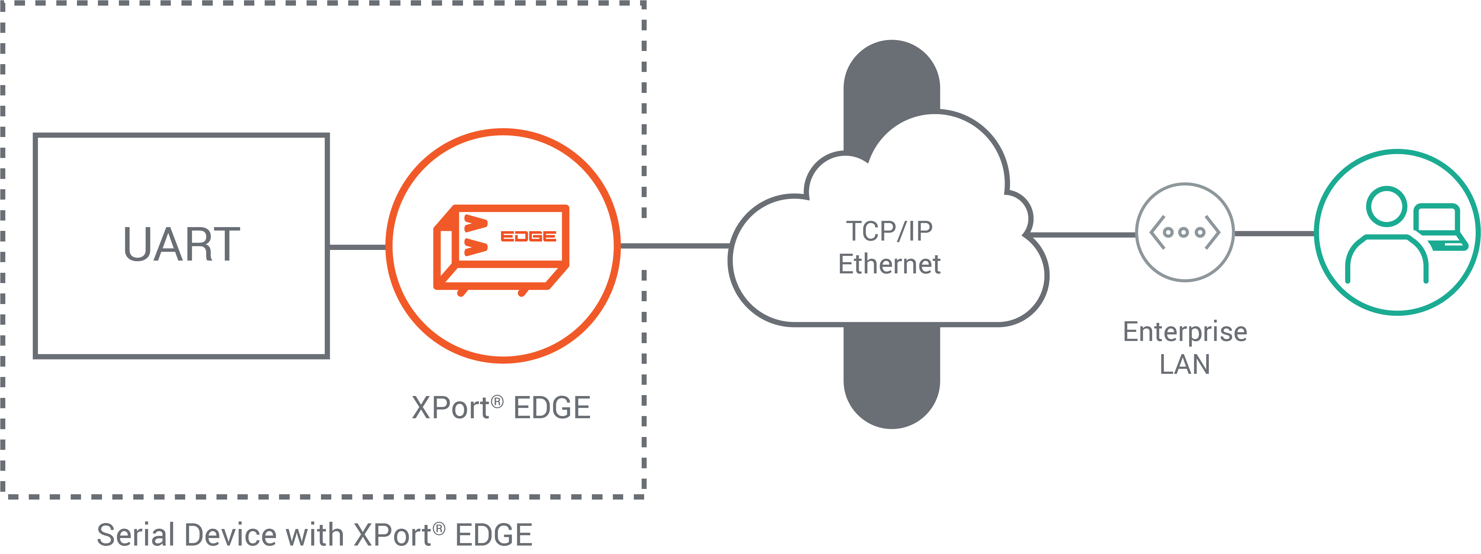
LAN Uplink
XPort EDGE Embedded Ethernet Gateway uses the eth0 network interfaces as an uplink to the LAN. The connected device or gateway can communicate with different applications through this interfaces. The picture below provides a simplified view of this configuration:
Configuring the Network Interface
The network interfaces contain Interface and Link configuration and status settings. The Interface configuration contains properties that are related to the IP layer associated with that network interface. The Link configuration contains properties related to the data link layer (Layer 2) characteristics of that network interface. The status settings show the interface and link status on the device.
Ethernet
The Ethernet interface enables the Lantronix gateway to connect quickly to an Ethernet network. When the DHCP client is enabled, the network DHCP server will assign an IP address.
Note
All network settings require a reboot to take effect.
Use one of the following methods to set up the Ethernet interface:
In the Web Manager, go to Network > eth0 > Interface.
For CLI, see Config Interface Level
For XML, see configgroup interface
Network eth0 Interface Configuration Settings
The following table describes the Web Manager Network eth0 Interface Configuration settings.
Links to the equivalent settings for the CLI and XML reference are listed below.
CLI settings: See Config Interface Level
XML settings: See configgroup interface
| Network eth0 Interface Settings | Description |
|---|---|
| Hostname | Host name may contain up to 63 characters. |
| MSS | Maximum Segment Size quantity in bytes. The MSS quantity applies to TCP connections on the Interface. This can be useful to avoid fragmentation over the network, which may be required because this device does not perform reassembly. |
| DHCP Client | Enable or disable the DHCP Client. |
| IP Address | IP Address. If not using the DHCP capabilities of the device, enter the static IP address to use for the interface. You may enter it alone (i.e., 192.168.1.1), in CIDR format (i.e., 192.168.1.1/24), or with an explicit mask (i.e., 192.168.1.1 255.255.255.0). |
| Default Gateway | Default Gateway. |
| DNS | This setting allows configuration of the DNS server address when the network address is obtained dynamically. Works on any interface where DHCP is configurable. Set to Static to specify DNS server IP address, or set to DHCP to let DHCP server determine DNS server address. |
| Primary DNS | Primary DNS IP address. |
| Secondary DNS | Enter the Secondary DNS IP address. |
| IPv6 State | Enable or disable IPv6 on eth0. |
| DHCPv6 Client | Enable or disable the DHCP IPv6 Client. |
| IPv6 Auto Configuration | Enable or disable IPv6 Stateless Address Auto Configuration. |
| IPv6 Address | IPv6 Address. |
| IPv6 Default Gateway | Default Gateway for IPv6. |
| IPv6 Primary DNS | Primary DNS for IPv6. |
| IPv6 Secondary DNS | Secondary DNS for IPv6. |
Link Setup
The Ethernet link speed can be configured to automatic negotiation, 10 Mbps, or 100 Mbps. When not configured for automatic negotiation, the duplex mode can be set for half- or full-duplex mode.
In the Web Manager, go to Network > eth0 > Link > Configuration to configure the link settings. After you save the changes, re-establish connections on the Ethernet link.
For the CLI, see Config Ethernet level
For XML, see configgroup Ethernet
Link Configuration Settings
The following table describes the Web Manager Network eth0 Link Configuration settings.
| Network eth0 Link Configuration Settings | Description |
|---|---|
| Speed | This is the speed of the Ethernet interface. Choices: Auto, 10 Mbps, 100 Mbps. The default is Auto. The Duplex option appears if you select 10 or 100. |
| Duplex | Duplex mode of the Ethernet interface. Choices: Half or Full. The default is Half. Duplex is required only when Speed is set not set to Auto. |
| EAP Authentication | When enabled, uses EAP authentication for the interface. |
| IEEE 8021X | The 8021X protocol. Choices are EAP-TLS, EAP-TTLS, PEAP, and FAST. This configuration option becomes available only when EAP Authentication is enabled. |
| Username | Username for login. This configuration option becomes available when EAP Authentication is enabled. |
| Password | Password for login. This configuration option becomes available when IEEE 8021X is set to EAP-TTLS, PEAP, or FAST. |
| Credentials | The TLS credential to authenticate. This configuration option becomes available when IEEE 8021X is set to EAP-TLS or EAP-TTLS. |
| EAP-TTLS Option | EAP-TTLS option to use from the drop-down menu. Choices are EAP-MSCHAPV2, MSCHAPV2, MSCHAP, CHAP, PAP, or EAP-MD5. This configuration option becomes available when IEEE 8021X is set to EAP-TTLS. |
| PEAP ver | PEAP version to use from the drop-down menu. Choices are 0 or 1. This configuration option becomes available when IEEE 8021X is set to PEAP. |
| PEAP Option | PEAP option to use from the drop-down menu. Choices are EAP-MSCHAPV2, EAP-MD5, or EAP-TLS. This configuration option becomes available when IEEE 8021X is set to PEAP. |
| PEAP Credentials | The TLS credential to authenticate. This configuration option becomes available when PEAP Option is set to EAP-TLS. |
| FAST Option | FAST option to use from the drop-down menu. Choices are MD5, MSCHAPV2, or GTC. This configuration option becomes available when IEEE 8021X is set to FAST. |
Loopback Interface
The loopback interface (lo0) is a virtual network interface on the XPort EDGE that lets you connect one network service to another on the same device. The SNMP extended agent uses the loopback interface, for example, to forward SNMP packets to the TCP host port on the xPort EDGE.
To configure the loopback interface:
In Web Manager, go to Network > lo0 > Interface > Configuration.
For CLI, see Config Interface level.
For XML, see Configgroup Interface.
| Loopback lo0 Interface Configuration | Description |
|---|---|
| State | Enabled or Disabled. Enabled allows the interface to operate. |
| Priority | When performing TCP or UDP connect, the Interface with 1 will be attempted first, 2 will be attempted second, etc. By default all Interfaces have Priority 1 and Ethernet interfaces are attempted before WLAN. |
| MSS | Maximum Segment Size quantity in bytes. The MSS quantity applies to TCP connections on the Interface. This can be useful to avoid fragmentation over the network, which may be required because this device does not perform reassembly. Default is 1460 bytes. Enter a range between 536 to 1460 bytes. |