PCB Footprint & Dimensions
Recommended PC Board Layout
The hole pattern and mounting dimensions for the XPort EDGE unit are shown in the following drawing:
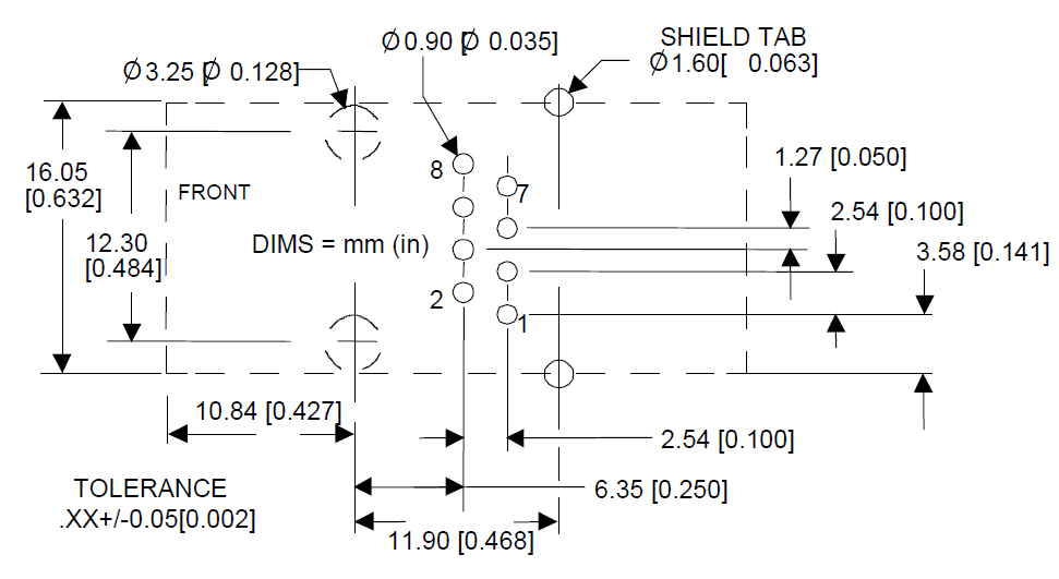
For proper heat dissipation, the PCB should have approximately 1 square inch of copper attached to the shield tabs. The shield tabs are an important source of heat sinking for the device.
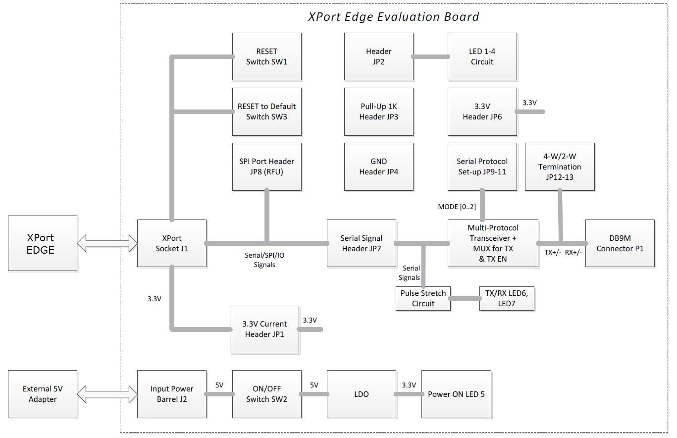
Evaluation Board Block Diagram
Evaluation Board Schematics
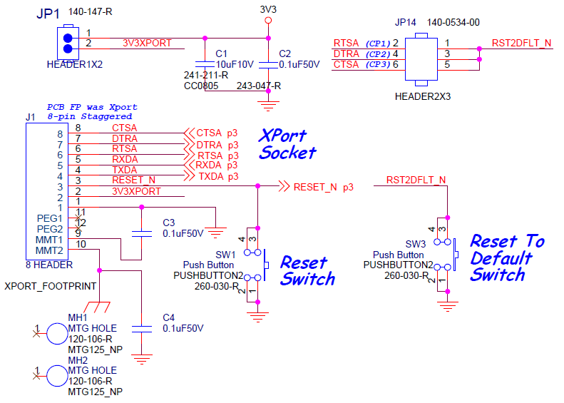
XPort EDGE Interface
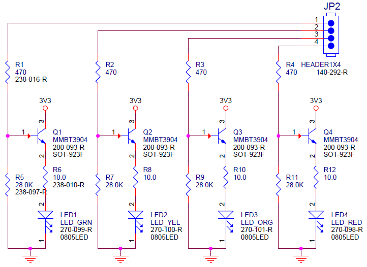
LED Circuit and Header
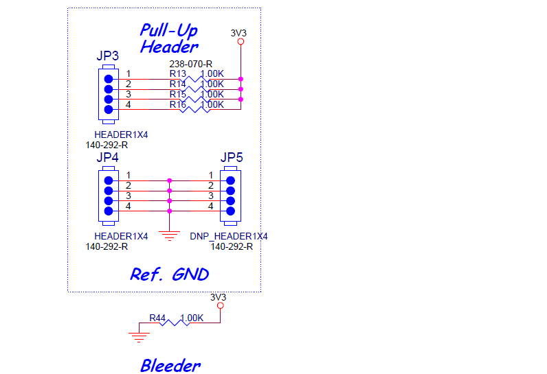
Pull-Up Header
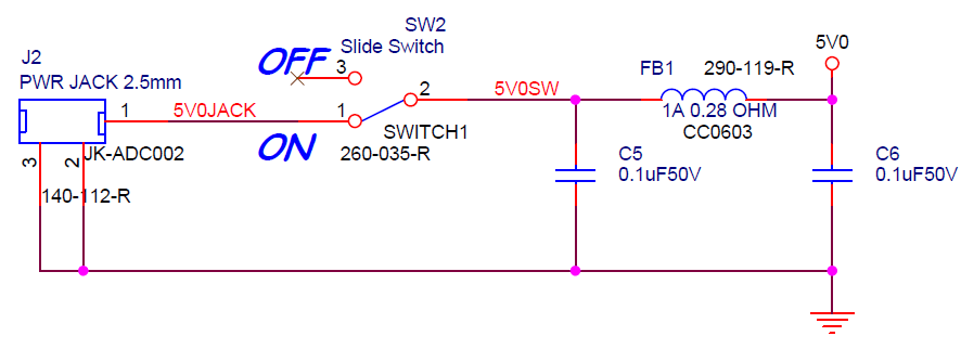
Power ON/OFF Switch
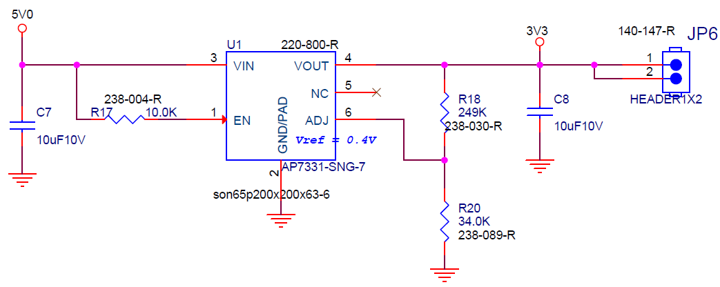
LDO for 3.3V
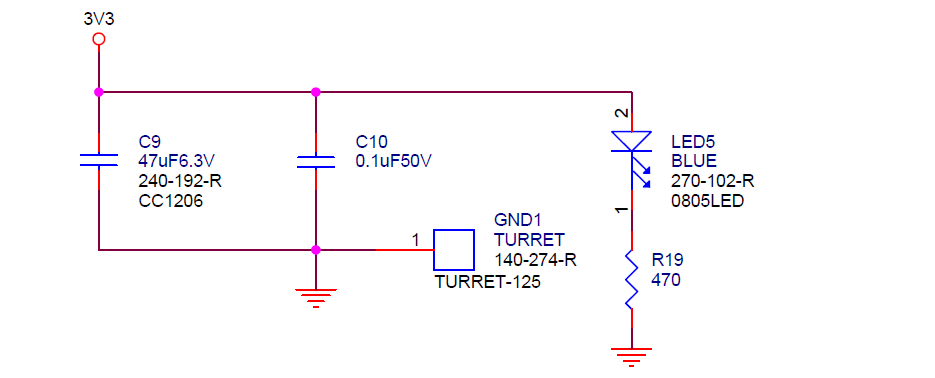
3v3 Power LED
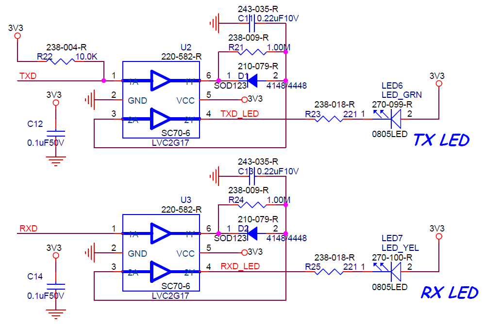
Serial Activity LEDs
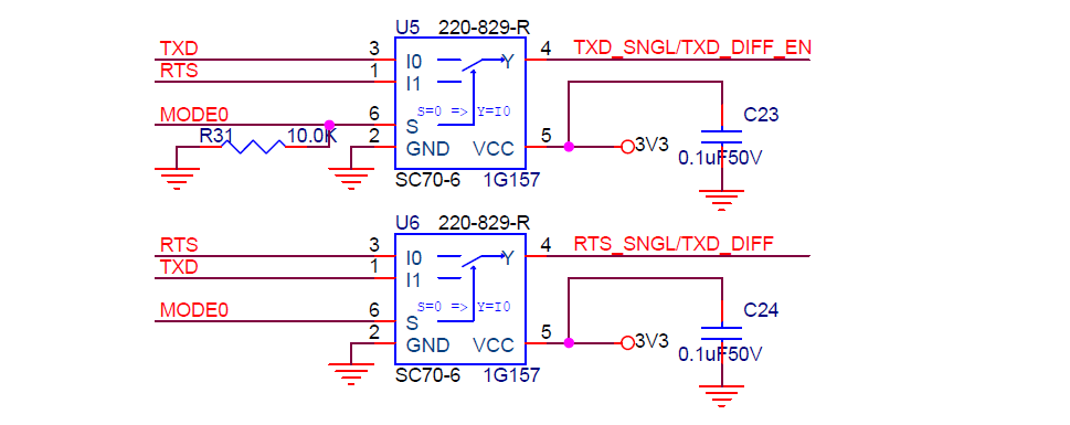
Mux for RS232/485 Signals
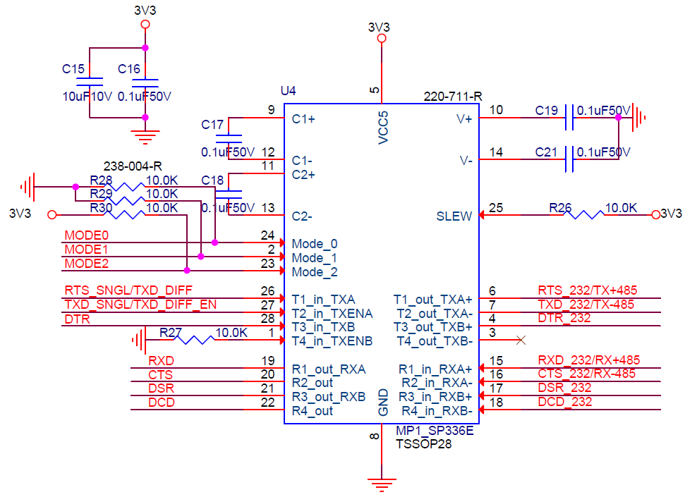
RS232/485/422 Transceiver
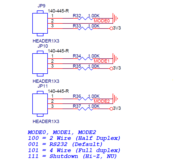
Protocol Setup Headers
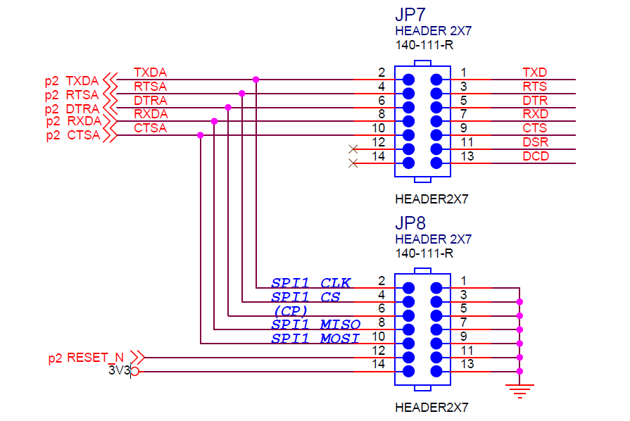
Serial/SPI Signals and Headers
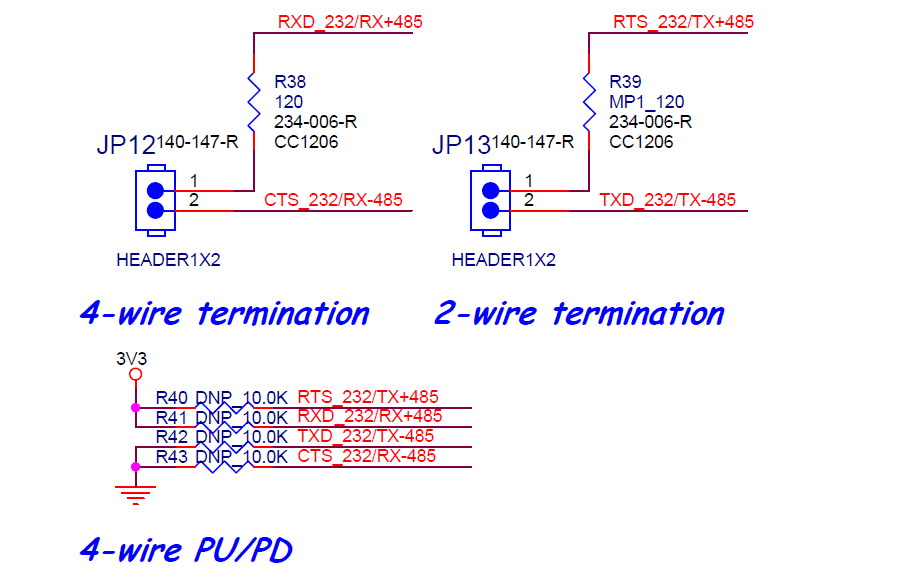
2-Wire / 4-Wire Ohm Termination Jumpers
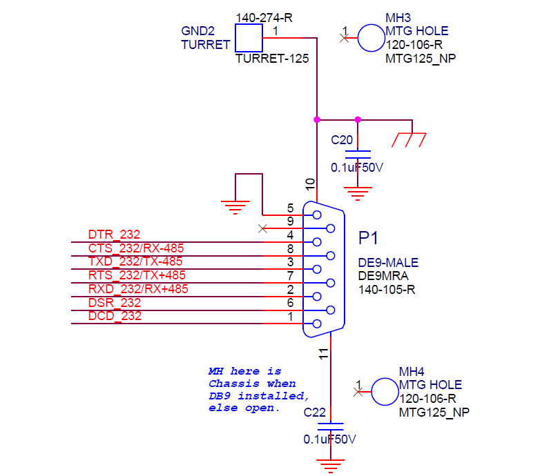
Serial Connector DB9M