Functional Description
XPort EDGE is the next generation of the world’s best-selling embedded Ethernet device server that provides full IoT gateway connectivity to any device with serial capability. By embedding XPort EDGE into a product design, manufacturers can offer secure network connectivity with integrated device management and cloud connectivity within weeks.
With customer proven TruPort technology that includes production-ready essential IoT connectivity firmware, cloud-based management and an integrated device security framework, xPico 200 series delivers a complete network and IoT connectivity offload solution for any microcontroller.
Device manufacturers can also partition their system design by extending the capabilities of XPort EDGE with custom application firmware that works together with the host microcontroller within their devices.
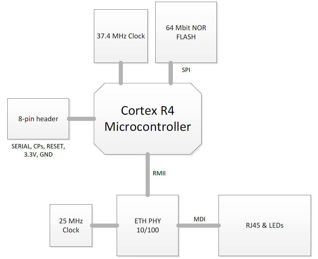
XPort EDGE Block Diagram
The block diagram of the XPort EDGE embedded Ethernet gateway shows the relationship between components.
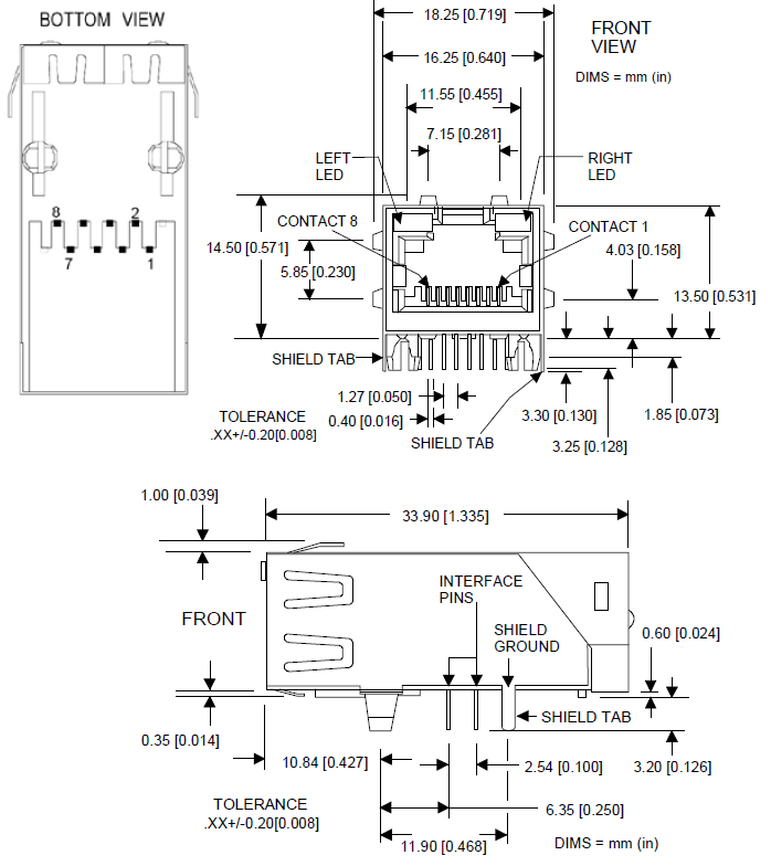
Dimensions
Features
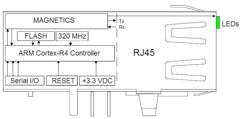
The XPort EDGE is built on a 32-bit ARM Cortex-R4 processor with 320 MHz clock, 2MB SRAM, 640 KB Boot ROM and 8 MB NOR FLASH, and an Ethernet 10/100 PHY with HP Auto-MDIX support.
The XPort Edge has the following for external interface:
- Single supply 3.3V powered module
- Auto detection of Ethernet 10/100 Base
- Integrated Ethernet Magnetics with HP Auto-MDIX support (works with either straight or cross Ethernet cables)
- Ethernet LED indicators for Link, Speed, and Activity
- 3.3V serial interface with multi-protocol RS232/485 (4-wire/2-wire) capability.
- Serial Hardware Handshake signals RTS, CTS, DTR pins
- 3 configurable IO pins (CPx) or any one CP can be configured as the Default# pin if the serial hardware handshake signals are not used
- Reset pin input
Signal Descriptions
The XPort EDGE is powered by a single supply 3.3V with a RESET (active low) input. For interfacing with the target system, it has a serial port configurable with data rates up to 4 Mbps. All signals including RESET are 3.3V. For applications requiring an external cable running with RS-232/RS-485 voltage levels, the XPort EDGE must be connected to a serial transceiver chip. For this purpose, we supply a multi-protocol transceiver on the XPort Universal Demo Board.
PCB Interface Signals
| xPort EDGE Pin # | Signal Name | Primary Function |
|---|---|---|
| 1 | GND | Circuit ground |
| 2 | 3.3V | Power in |
| 3 | RESET | External Reset in |
| 4 | Data Out | Serial data out |
| 5 | Data In | Serial data in |
| 6 | RTS | RTS output in RS-232 mode, driven by built-in UART TX enable in RS-485 mode, driven by built-in UART |
| 7 | DTR | DTR output, driven by built-in UART |
| 8 | CTS | CTS input, read by built-in UART |
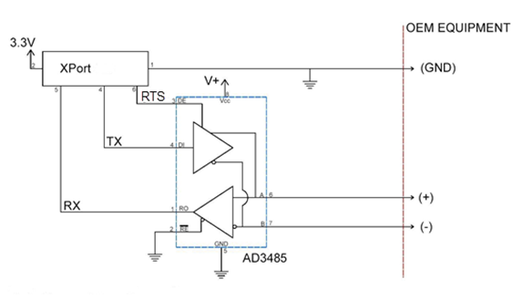
Connection Diagram
The following example illustrates a connection between the xPort EDGE Embedded Ethernet Gateway and an external transceiver IC:
Module Power
The XPort EDGE series operates on 3.3V power with 3.3V logic in an extended temperature range. See the XPort EDGE Embedded Device Server Data Sheet available at https://www.lantronix.com/products/xport-edge/ for more details on module power.