Evaluation Kit Contents
The Lantronix xPico 200 series allows OEMs to go to market faster with their smart connected products. It delivers seamless and secure Ethernet, Wi-Fi and/or Bluetooth connectivity. Featuring advanced enterprise security, complete Wi-Fi, network and Bluetooth stack offload, essential applications for data connectivity and control, and pre-integration with the Percepxion™ platform, the xPico 200 series delivers embedded gateway capability in an industry-leading compact footprint.
The evaluation kit is available in the following variants depending on the xPico 200 series model that is mounted:
- XPC240300EK - xPico 240 module (Ethernet + Wi-Fi)
- XPC240400EK - xPico 240 module (Ethernet + Wi-Fi)
- XPC250300EK - xPico 250 module (Ethernet + Wi-Fi + Bluetooth)
- XPC270300EK - xPico 270 module (Ethernet + Wi-Fi with 802.11ac + Bluetooth)
Evaluation Kit Contents:
- xPico 200 module (xPico 240, xPico 250, or xPico 270 model) on an edge card
- xPico 200 evaluation board with socket for xPico 200 edge card module
- 5V DC power supply adapter (with international plugs)
- 2x Antennas with U.FL to R-SMA adapter cable (XPC240300EK, XPC250300EK, XPC270300EK only. XPC240400EK includes an on-module antenna.)
Evaluation Kit Description
The xPico 200 evaluation kit provides a test platform for the Lantronix xPico 200 gateway module. The evaluation kit uses either 5V power from a USB device port connector or power supplied 5V barrel connector. The evaluation kit includes all necessary regulators to power the 3.3V xPico 200 module.
The evaluation kit has the following features:
- One DB9M serial port connector with an RS232 transceiver at rates up to 1 Mbps
- One RJ45 10/100 Ethernet port with on board PHY and magnetic module
- One mini-type B USB device port connector for 5V input power and device port connection to the xPico 200 module. This port can also be jumpered to act as a Host port for engineering evaluation. Refer to the xPico 200 Series Embedded Wi-Fi Gateway Integration Guide and USB.org for proper USB compliant host port implementation.
- LEDs for the xPico Ethernet and system status outputs
- Access to all logic level IO signals on the xPico 200 via header pins for measurements and connections to other places
The xPico 240/250/270 evaluation board image shows the xPico 200 evaluation kit with an attached xPico 200 module, highlighting all of the connectors and configuration jumpers. The Connectors, Header and Switches table lists each of the connectors and jumper headers along with their function. Further description and pin assignments are included in subsequent sections.
xPico 200 Evaluation Board
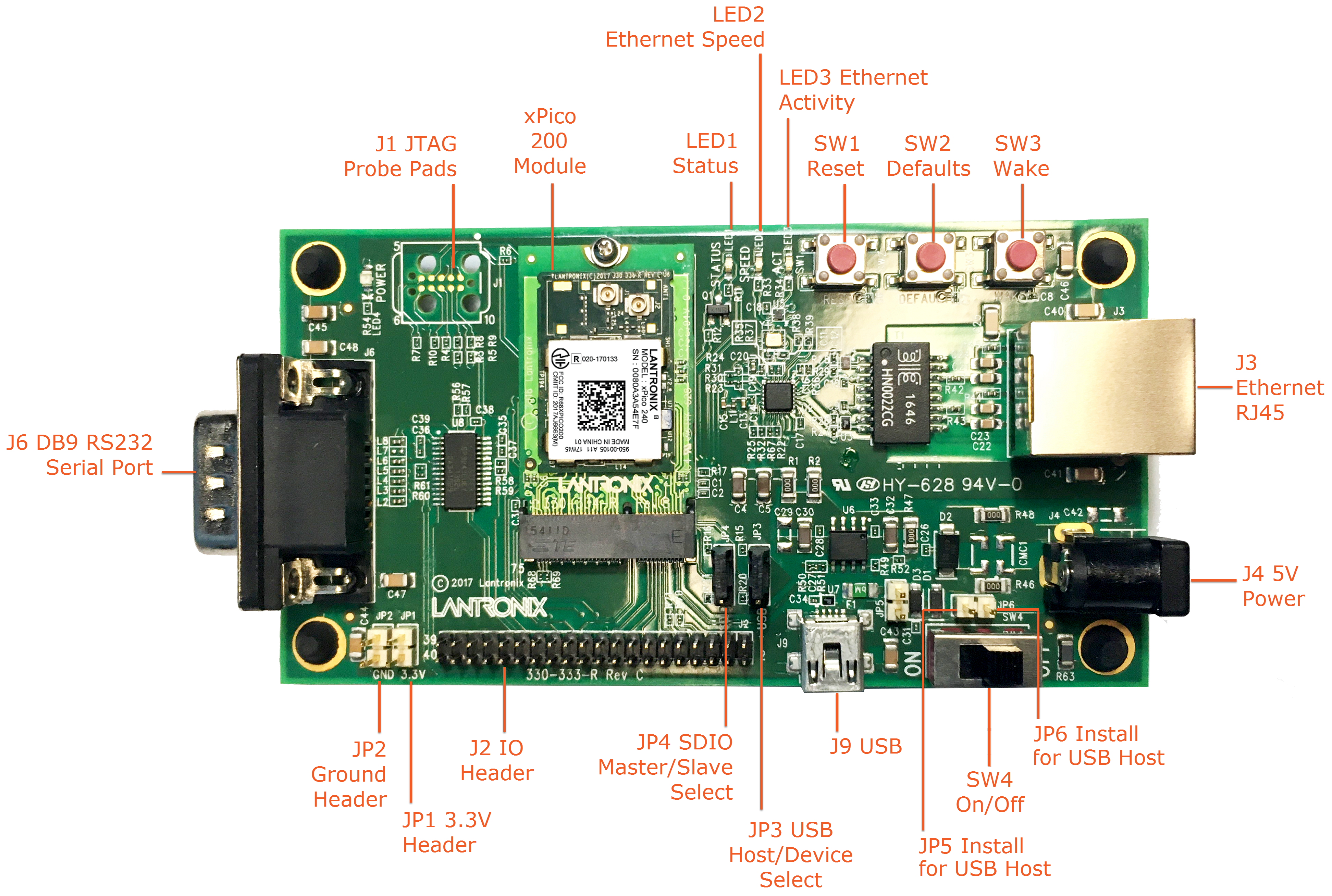
Connectors, Headers and Switches
| Ref. Description | Connector/Header Functions |
|---|---|
| JP1 | 3.3V Power Header Test point to monitor the 3.3V regulator output. |
| JP2 | Ground Header Test point to connect to evaluation board signal ground. |
| JP3 | USB Host/Device Select Install Jumper to pins 1 to 2 for USB Device Mode Install Jumper to pins 2 to 3 for USB Host Mode (Host mode also requires jumper install on JP5, JP6 to provide power out of J9) |
| JP4 | SDIO Master/Slave Select Install Jumper pins 1 to 2 for SDIO Master Mode Install Jumper pins 2 to 3 for SDIO Slave Mode |
| JP5 | USB Host Power Out Jumper Install to provide power out for USB host mode. Do not install for device mode (default) |
| JP6 | USB Host Power Out Jumper Install to provide power out for USB host mode. Do not install for device mode (default) |
| J1 | JTAG Pads Install JTAG pogo pin header at J1. Use Tag-Connect TC2050-IDC cable probe and TC2050-ARM2010 adapter for JTAG connections |
| J2 | IO Pin Header Header for connection to module power, serial port, and configurable pin connections. |
| J3 | Ethernet RJ45 |
| J4 | 5V Barrel Connector Input port for 5V board power |
| J6 | DB9 RS232 Serial Port |
| J9 | Module USB Port Defaults to USB device port. Jumper options available to run as a host port. |
Serial Interface
The evaluation kit has one RS232 port for connection to the xPico 200 internal UART. Serial port 1 is a DB9M (DTE) connector labeled J6. The null modem cable can be used to connect J6 directly to a standard PC RS232 serial port.
RS-232 Signals on J6 Serial Interface
| xPico 200 Evaluation Kit Pin Function Serial Port |
DB9M Pin Number |
|---|---|
| TX_232 (Data Out) | 3 |
| RX_232 (Data In) | 2 |
| CTS_232 (HW Flow Control Input) | 8 |
| RTS_232 (HW Flow Control Output) | 7 |
| DTR_232 (Modem Control Output) (Populate R56) |
4 |
| DCD_232 (Modem Control Input) (Populate R57) |
1 |
| GND (Ground) | 5 |
Note
The evaluation board is configured for RS232 on the UART signals. If attempting to use the J2 UART TTL header pins instead of the RS232 transceiver, pin 22 of the serial transceiver (U8) should be tied to ground.
Ethernet Interface
The xPico 200 evaluation kit includes one RJ45 connector with on-board magnetics for connection to the xPico 200 module 10/100Mbps Ethernet interface. Connector J3 is the Ethernet port.
Power Supply
The evaluation kit provides multiple input Power Options. Included with the kit is a 5V wall adapter which plugs into barrel connector J4. In addition to powering from the wall adapter, the evaluation kit can be powered from a standard PC USB Host port by connecting a USB cable between the PC and J9. If powered via USB, the unit must be configured for USB device mode (JP3 pins 1 to 2, JP5 out, JP6 out).
Power Options
| Input Power Option | Description |
|---|---|
| 5V Wall Cube | Connect 5V wall cube to the J4 barrel connector. |
| USB (device mode, power input) | Connect J9 USB power to a PC USB Host Port. Note: For J9 Note unit must be configured for USB device mode (JP3 pins 1 to 2, JP5 out, JP6 out.) |
LEDs
The xPico evaluation kit includes several LEDs to communicate module, Ethernet activity, or power status. The LED Signals table lists all LEDs and their functions.
LED Signals
| J7 Pin | LED Ref Design | Color | LED Function |
|---|---|---|---|
| 6 | LED1 | Orange | xPico 200 Status LED blinks with patterns indicating module status. See the Status LED1 Blink Patterns table below for a full description of the status LED blink patterns. |
| None | LED2 | Orange | Ethernet Link Status LED is ON when there is a valid Ethernet link at 100 Mbps |
| None | LED3 | Orange | Ethernet Activity LED blinks when there is activity on the Ethernet port |
| None | LED4 | Blue | 3.3V Power LED LED is ON when evaluation board 3.3V power is up. |
Status LED1 Blink Patterns
| Blink Pattern | Code | Error |
|---|---|---|
| 1 long, 2 short | E12 | No flash image found |
| 1 long, 3 short | E13 | Bad flash image found |
| 1 long, 4 short | E14 | Bad command parameter |
| 1 long, 8 short | E18 | Reception timeout |
| 2 long, 1 short | E21 | Image oversize |
| 2 long, 2 short | E22 | Bad image checksum |
| 2 long, 3 short | E23 | Bad image destination |
| 2 long, 4 short | E24 | Internal coding problem |
| 2 long, 5 short | E25 | Bad image header |
| 2 long, 6 short | E26 | Secure image not signed |
| 2 long, 7 short | E27 | Secure image failed verify |
J2 Header Pins
The J2 Pin Header table lists the pin functionality of the additional evaluation kit headers. Included is the J7 connection to the xPico 200 edge module connector.
J2 Pin Header
| J7 Module Pin | J2 Header Pin | Signal | Function | Secondary Functions |
|---|---|---|---|---|
| N/A | 2,4,6 | VIN | Evaluation board 5V power | |
| 1,7,18,33, 9,45,51,57, 63,69,75 |
1,3,5,33, 35,37,39 |
Ground | Evaluation board Ground | |
| 2,4,72,74 | 34,36,38,40 | 3V3(M) | Evaluaton board 3.3V power | Routes to J7 module pins via R1 |
| 50 | 7 | CP1 | Configurable pin 1 | USB host mode over-current flag input |
| 48 | 9 | CP2/INT | Configurable pin 2 | SPI interrupt input USB host mode port power enable output |
| 46 | 11 | CP3 | Configurable pin 3 | SPI-MISO |
| 44 | 13 | CP4 | Configurable pin 4 | SPI MOSI |
| 58 | 15 | CP5 | Configurable pin 5 | I2C Data |
| 60 | 17 | CP6 | Configurable pin 6 | I2C clock |
| 42 | 19 | CP7 | Configurable pin 7 | SPI Clock |
| 40 | 21 | CP8 | Configurable pin 8 | SPI Chip Select |
| 9 | 8 | SDCLK | SDIO Clock | |
| 11 | 10 | SDCMD | SDIO Command | |
| 13 | 12 | SDIO0 | SDIO Data 0 | |
| 15 | 14 | SDIO1 | SDIO Data 1 | |
| 17 | 16 | SDIO2 | SDIO Data 2 | |
| 19 | 18 | SDIO3 | SDIO Data 3 | |
| 56 | 20 | I2C Data 2 | I2C Bus 2 Data | |
| 54 | 22 | I2C Clock 2 | I2C Bus 2 Clock | |
| 16 | 24 | CP9 | Configurable pin 9 | PWM Output |
| 62 | 26 | CP10 | Configurable pin 10 | PWM Output |
| 22 | 27 | TXD1 | UART transmit data output | |
| 34 | 28 | RTS1 | UART ready to send output | |
| 32 | 29 | RXD1 | UART receive data input | |
| 36 | 30 | CTS1 | UART clear to send input | |
| 23, 25, 31, 32 | No connect | Reserved-Do not connect |
Please refer to the xPico 200 Series Embedded Wi-Fi Gateway Integration Guide for evaluation board schematics.
Buttons
| Button | Signal | J7 Module pin | Button Function |
|---|---|---|---|
| SW1 | EXT_RESET# | 52 | Module Hardware Reset Button assertion reboots the module |
| SW2 | DEFAULTS | 23 | Module Reset to Defaults Assert for 6 seconds upon boot up to reset the xPico 200 module to factory defaults |
| SW3 | WAKE | 20 | Module Wake Up Button assertion will wake up the xPico 200 module from standby or sleep states. Requires the function to be enabled on the module. See the xPico 200 Series Embedded Wi-Fi Gateway User Guide for more information on low power states. |