Functional Description
The xPico 200 series delivers always-on dual-band enterprise Wi-Fi, dual-mode Bluetooth (Bluetooth Classic v2.1+EDR and Bluetooth Low Energy v4.2) as well as Ethernet connectivity for business-critical assets.
It is a standalone module that does not require an external host processor for the wireless and network stack. With customer proven TruPort technology that includes essential IoT connectivity firmware, cloud-based management and an integrated device security framework, xPico 200 series delivers a complete network and IoT connectivity offload solution for any microcontroller.
xPico 200 series offer three main models depending on the connectivity interfaces available:
- xPico 240 - provides dual-band Wi-Fi and Ethernet combo
- xPico 250 - provides dual-band Wi-Fi, Ethernet and dual-mode Bluetooth (Bluetooth Classic and Bluetooth Low Energy)
- xPico 270 - provides dual-band Wi-Fi with 802.11ac, Ethernet and dual-mode Bluetooth (Bluetooth Classic and Bluetooth Low Energy)
The xPico 200 comes in two form factors:
- Small form factor SMT module-
- Edge connector module with standard connector
Block Diagram
The block diagram of the xPico 200 gateway below shows the relationship between components.
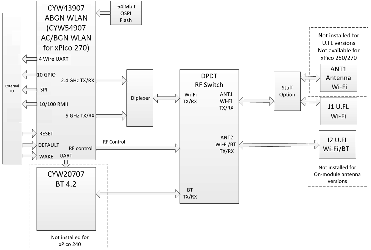
Note
Bluetooth is not available for modules with integrated antenna.
Features
The xPico 200 series embedded gateways are built around Cypress Semiconductor's Wi-Fi and Bluetooth SoC. Network connections are provided by a dual band 802.11 a/b/g/n/ac WLAN radio, BT4.2 radio, and a 10/100Mbps Ethernet MAC. The xPico 200 gateway includes the following:
- 802.11 a/b/g/n/ac wireless with option for on-module antenna or dual U.FL connectors
- One 10/100 Mbps Ethernet MAC (RMII)
- One USB 2.0 high speed interface (Host mode)
- One TTL UART interface with RTS/CTS
- One SPI interface (Master Mode, 24 MHz)
- One SPI interface (Slave Mode)
- Up to 10 configurable GPIO pins
- 3.3V power connection and logic IO
- Internal reset circuit
- Integrated wake up and shutdown for standby state
The xPico 200 gateway requires +3.3V DC power and is designed to operate over an extended temperature range. For detailed technical and compliance specifications please refer to the xPico 200 Series Embedded Wi-Fi Gateway Data Sheet at the Lantronix xPico 240 product page, the Lantronix xPico 250 product page, and the Lantronix xPico 270 product page.
xPico 200 Dimensions and Views, SMT Version
SMT (LGA) Footprint with Dual U.FL Antenna
SMT footprint makes it suitable for employing efficient and cost effective manufacturing processes. The compact footprint (17 x 25 mm) makes it easy to integrate within designs that have space constraints.
Dual U.FL antennas offer Wi-Fi diversity (xPico 240) and independent antennas for Wi-Fi and Bluetooth operation (xPico 250 and xPico 270). They are suitable for external stub antennas or for use with PCB strip antennas for keeping everything internal to the product enclosure.
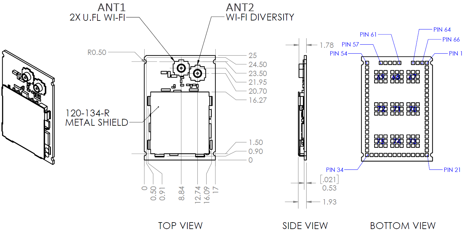
Note
Wi-Fi diversity is not available on units with Bluetooth.
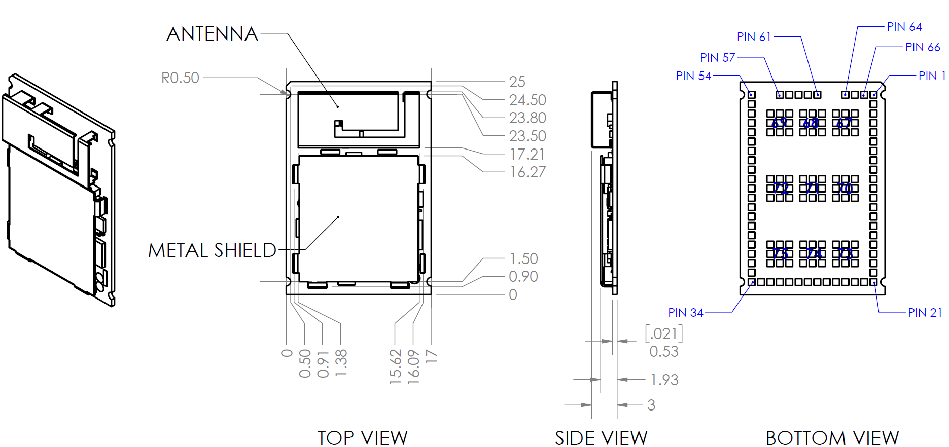
SMT (LGA) Footprint with On-Module Antenna
On-module antenna removes the need for additional antennas. This option is available only for xPico 240 (Wi-Fi only configuration).
This variant is suitable when a single antenna may be sufficient or there is no space for additional antennas.
xPico 200 Dimensions and Views, Edge Connector Version
The edge connector footprint makes it easy to integrate into a design where connectivity is optional or using a B2B connector interface allows components to be placed underneath.
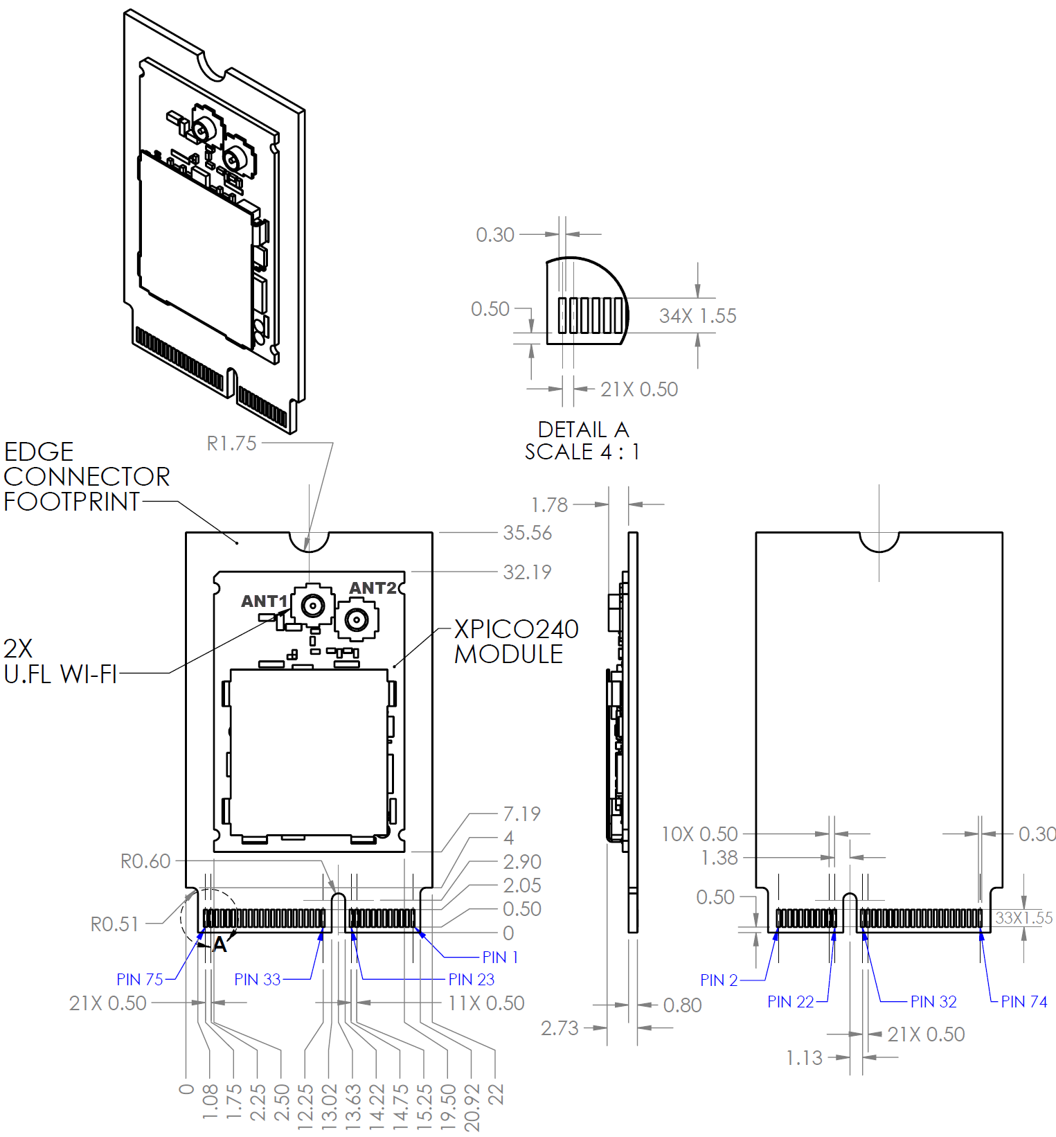
The Edge Connector Module mates to TE Connectivity part number 2199230-4. This connector is mechanically equivalent to an E-keyed M.2 type mating interface. Alternate M.2 mating connectors with an E-key such as JAE part number SM3ZS067U410AER1000 can be used.
Note
The xPico 240, xPico 250, and xPico 270 edge connector module has a different pinout from the M.2 specification. Please refer to and use only the signal pinouts specified in the integration guide for your layout.
Signal Descriptions
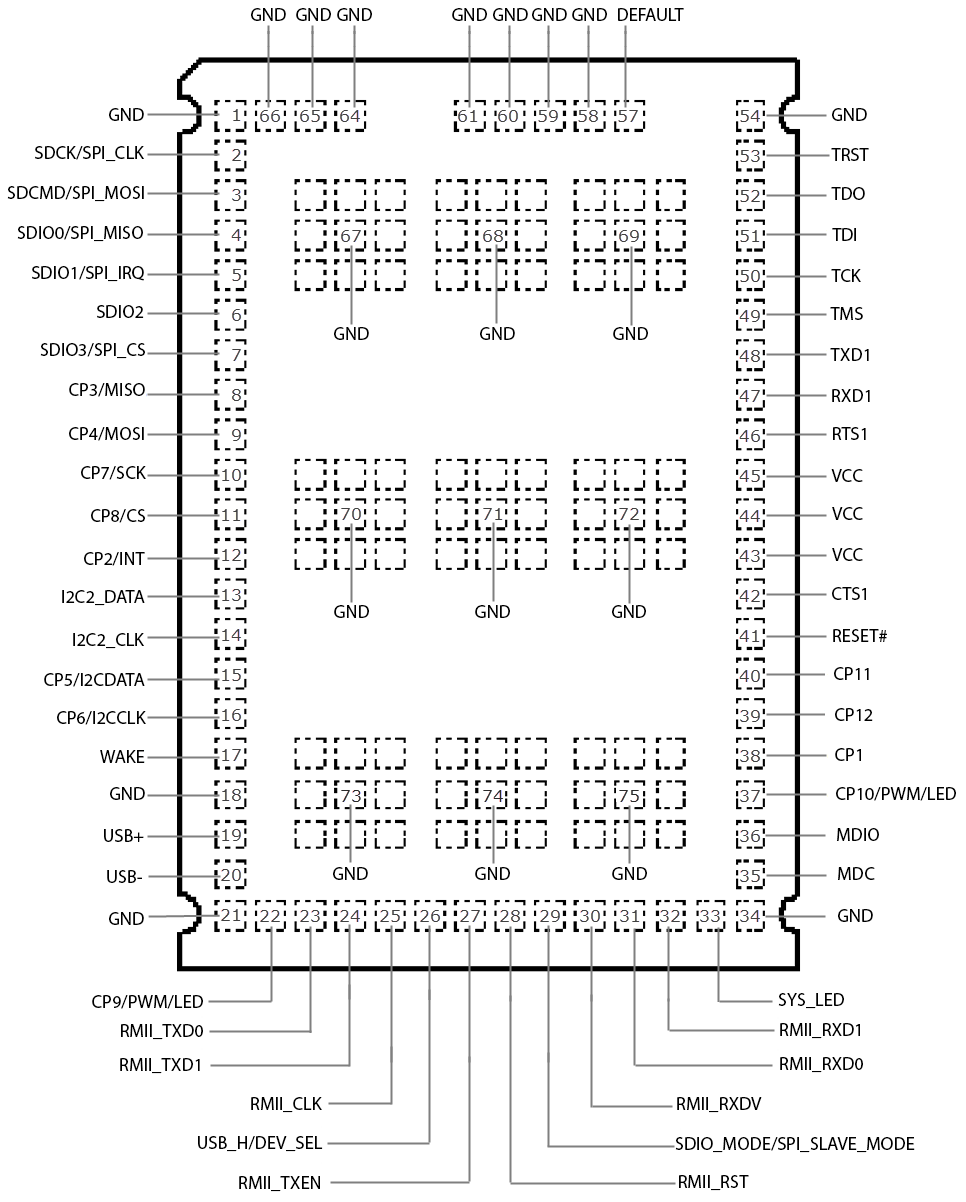
xPico 200 Edge Connector Pin and Signal Location

xPico 200 Edge Connector Footprint Pin and Signal Description
| Pin | Signal | Pin | Signal | |
|---|---|---|---|---|
| 1 | GND | 2 | 3.3V | |
| 3 | USB_D+ | 4 | 3.3V | |
| 5 | USB_D- | 6 | SYS_LED | |
| 7 | GND | 8 | NC | |
| 9 | SDIO_SCK/SPI_CLK (slave) | 10 | NC | |
| 11 | SDIO_CMD/SPI_MOSI (slave) | 12 | USB_H/D_SEL | |
| 13 | SDIO_DATA0/SPI_MISO (slave) | 14 | SDIO_MODE/SPI_SLAVE_MODE | |
| 15 | SDIO_DATA1/SPI_IRQ (slave) | 16 | CP9/LED | |
| 17 | SDIO_DATA2 | 18 | GND | |
| 19 | SDIO_DATA3/SPI_CS (slave) | 20 | WAKE | |
| 21 | NC | 22 | UART_TXD | |
| 23 | DEFAULT# | 32 | UART_RXD | |
| 33 | GND | 34 | UART_RTS | |
| 35 | TDO | 36 | UART_CTS | |
| 37 | TDI | 38 | TRST | |
| 39 | GND | 40 | CP8/CS (master) | |
| 41 | TCK | 42 | CP7/SCK (master) | |
| 43 | TMS | 44 | CP4/MOSI (master) | |
| 45 | GND | 46 | CP3/MISO (master) | |
| 47 | RMII_MDC | 48 | CP2/INT (master) | |
| 49 | RMII_MDIO | 50 | CP1 | |
| 51 | GND | 52 | RESET# | |
| 53 | RMII_RXD1 | 54 | I2C2_CLK | |
| 55 | RMII_RXD0 | 56 | I2C2_DATA | |
| 57 | GND | 58 | CP5/I2C_DATA | |
| 59 | NC | 60 | CP6/I2C_CLK | |
| 61 | RMII_CLK | 62 | CP10/PWM | |
| 63 | GND | 64 | NC | |
| 65 | RMII_RXDV | 66 | RSVD_CP12 | |
| 67 | RMII_TXEN | 68 | RSVD_CP11 | |
| 69 | GND | 70 | RMII_RST | |
| 71 | RMII_TXD1 | 72 | 3.3V | |
| 73 | RMII_TXD0 | 74 | 3.3V | |
| 75 | GND |
xPico 200 LGA Footprint Pin and Signal Location
Pins 67 to 75 are the large pads under the module. Pins 67 to 75 must be connected to GND.
For xPico 200 PCB interface pin and signal descriptions, refer to the xPico 200 Series Embedded Wi-Fi Gateway Data Sheet at the Lantronix xPico 240 product page and the Lantronix xPico 250 product page.
Antenna Options
The xPico 200 gateway certifications are applicable when using the on-module antenna or the external antennas listed below. Per certification guidelines, the xPico 200 Wi-Fi certification remains valid if using an antenna similar to the antennas listed below. A valid antenna can have a different manufacturer part number but the antenna gain must be equal to or less than specified in the table. For detailed technical and compliance specifications, refer to the xPico 200 Series Embedded Wi-Fi Gateway Data Sheet at the Lantronix xPico 240 product page, the Lantronix xPico 250 product page, and the Lantronix xPico 270 product page.
xPico 200 Wi-Fi On-Module Antenna
The on-module antenna variant is single antenna only. There is no Bluetooth or Wi-Fi diversity. It maps to ANT1. xPico 200 firmware automatically sets the antenna configuration to ANT1 when operating inside the on-module antenna variant.
| Antenna Type | Lantronix Part Number |
Vendor | Vendor Part Number |
Approved Region |
|---|---|---|---|---|
| On-module antenna | N/A | N/A | N/A | FCC, IC, EU, AUS/NZS, JPN, China |
xPico 200 Series External Antenna Options
xPico 200 series dual U.FL variant enables connections to two antennas external to the gateway. The drawings refer to these as ANT1 and ANT2.
For xPico 240, they provide antenna diversity (in single stream mode). The xPico 240 module supports diversity when antennas are installed on both U.FL connectors. With diversity enabled in the firmware, the unit will check the received signal strength on each antenna port approximately every 310 ms when the signal level is below -20 dbm and when the average number of received packets is low. The unit does not poll the antennas during high traffic periods in order to maintain throughput.
A single antenna may be used in a design. Gateway configuration should be set to ANT1 or ANT2, depending on which U.FL connector has the antenna populated. For information on setting the antenna configuration, please refer to the xPico 200 Series Embedded Wi-Fi Gateway User Guide.
For xPico 250 and xPico 270, ANT1 is dedicated for Wi-Fi and ANT2 is dedicated for Bluetooth. Diversity is not available for xPico 250 or xPico 270. Bluetooth is only available for xPico 250 and xPico 270.
| Antenna Type |
Peak Gain Typical | Lantronix Part Number |
Vendor/ Part Number |
Approved Region |
|---|---|---|---|---|
| PCB Strip Antenna with 50 mm cable to U.FL connector With tape backing | 2.5dBi (2.39 to 2.49 GHz) 5 dBi (4.9 to 5.9 GHz) |
XPW100A003-01-B 50 piece bulk pack | Ethertronics/ 1001077 |
FCC, IC, EU, AUS/NZS, JPN, China |
| PCB Strip Antenna with 50 mm cable to U.FL connector Without tape backing | 2.5dBi (2.39 to 2.49 GHz) 5dBi (4.9 to 5.9 Ghz) |
Ethertronics/ 1000668 |
FCC, IC, EU, AUS/NZS, JPN, China | |
| Swivel type antenna, with RP-SMA(M) connector | 2 dBi (2.4 to 2.5 GHz) 2 dBi (5.15 to 5.85 GHz) |
ACC-930-033-R | Wanshih/ WSS002 |
FCC, IC, EU, AUS/NZS, JPN, China |
| Swivel type antenna, with RP-SMA(M) connector | 3.8 dBi (2.4 to 2.5Ghz) 5.5 dBi (4.9 to 5.8Ghz) |
Taoglas/ GW.71.5153 (Not for EU use) |
FCC, IC, AUS/NZS, JPN, China |
The PCB strip antenna is available from Ethertronics with or without adhesive tape backing for mounting to a plastic case. The antennas Lantronix supplies include an adhesive backing. For the component without tape backing, a non-conductive double-sided adhesive tape can be used to fix the antenna in place. The Ethertronics part numbers listed above come with a 50 mm U.FL cable attached to the PCB strip antenna. The 50 mm cable length is the minimum allowed cable length for use with the xPico 200 gateway. Consult Ethertronics for similar PCB strip antennas with longer cables.
Lantronix provides a U.FL to Reverse SMA antenna cable in with the evaluation board and sample kits for development work. These cables can be purchased from Lantronix for production or supplied by an RF cable manufacturer. External antennas can be purchased from an antenna vendor.
Antenna Selection Guidelines
- Components for cable design should be selected for low loss over the entire 2.4 GHz to 5.9 GHz signal range.
- The cable target impedance should be 50 ohms.
- The minimum allowed cable length for use with xPico 200 Gateway is 50 mm.
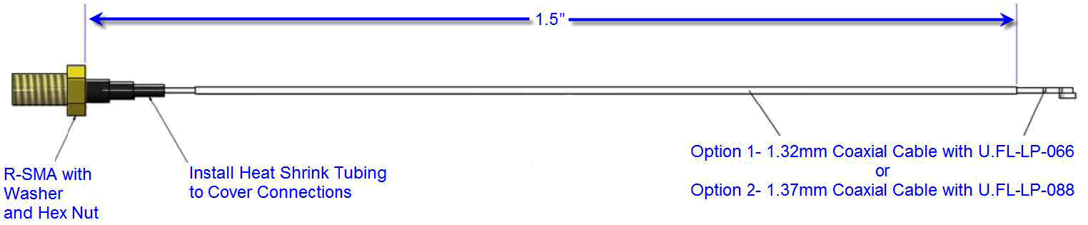
Reverse-SMA to U.FL (Long) (Lantronix Part Number 500-180-R-ACC)

U.FL to U.FL Cable (Lantronix Part Number 500-181-R-ACC)
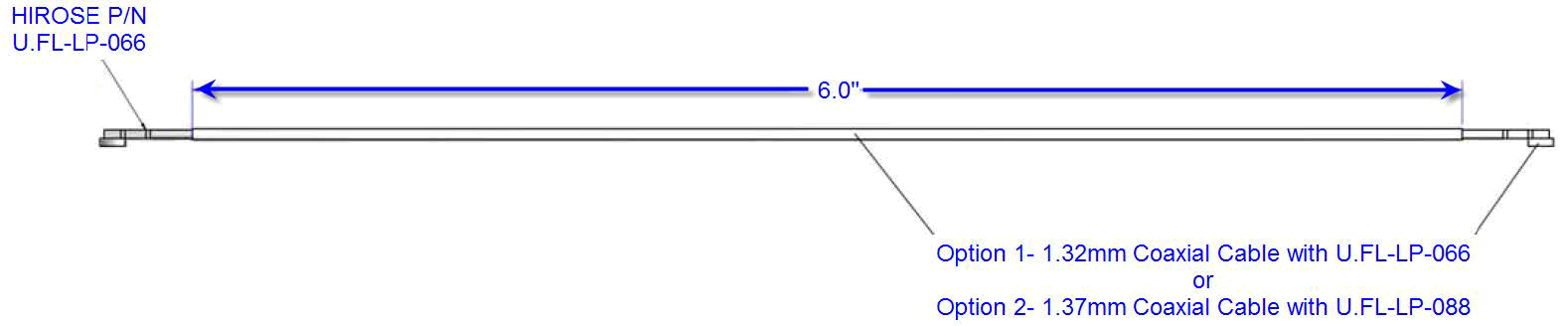
Reverse-SMA to U.FL (Short) (Lantronix Part Number 500-182-R-ACC)
Antenna Placement Recommendations
When designing the xPico 200 gateway to a mating board:
- Consider the final installation of the module and its location with respect to connecting access points. For maximum range, the antenna should be placed with the clearest possible path to the connecting access point. Avoid placing the antenna such that it is blocked by metal walls or ground planes of adjacent circuit boards.
- When using the on board antenna it is recommended to place the module such that the antenna region is along the edge or corner of the board. The areas noted under the antenna region should be voided of all signals and planes.
- See the figure images below showing recommended placement with the module chip antenna.
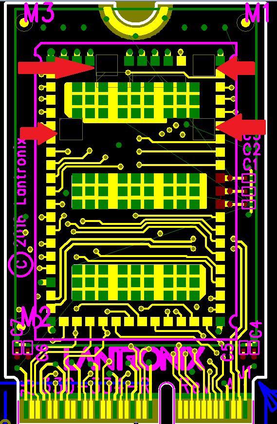
xPico 200 On-Module Antenna Board Edge Mounting
The red arrows in this diagram point out four square areas that should be voided in the mating board artwork. The evaluation kit artwork in PADs is available through the Platform PCB Package which can be downloaded at the Lantronix xPico 240 product page, the Lantronix xPico 250 product page, and the Lantronix xPico 270 product page.
UART Interface
The xPico 200 gateway has one external UART interface. The signal levels on the UART interface are 3.3V tolerant. The UART interface requires an external transceiver in order to connect to external RS232, RS485, or RS422 networks. The signals of the serial ports may be connected as shown in the Serial Port Example below.
The transceiver shown in the reference below is of type Exar, part number SP336. This transceiver is a multiprotocol RS232, RS485, RS422 transceiver. Single protocol transceivers may be used as required. The xPico 200 interface may also be directly connected to the UART interface of an external CPU.
UART Interface Signals
| Pin Name | Description | SMT Pin | Edge Connector Pin |
|---|---|---|---|
| TXD1 | Serial transmit data output | 48 | 22 |
| RXD1 | Serial receive data input | 47 | 32 |
| RTS1 | Serial ready-to-send / serial transmit enable output | 46 | 34 |
| CTS1 | Serial clear-to-send input | 42 | 36 |
UART Interface Example

Example: RS232 Serial Connection (Transceiver Required)
| xPico 200 Signal (Logic) |
Description | DTE DB9 |
DTE DB25 |
DTE Signal |
DCE DB9 |
DCE DB25 |
DCE Signal |
|---|---|---|---|---|---|---|---|
| RXD1 | Data In | 2 | 3 | RXD | 3 | 2 | TXD |
| TXD1 | Data Out | 3 | 2 | TXD | 2 | 3 | RXD |
| RTS1 | H/W Flow Control Output | 7 | 4 | RTS | 8 | 5 | CTS |
| CTS1 | H/W Flow Control Input | 8 | 5 | CTS | 7 | 4 | RTS |
| CPx | Modem Control Input | 1 | 8 | DCD | 4 | 20 | DTR |
| CPy | Modem Control Output | 4 | 20 | DTR | 1 | 8 | DCD |
Example: RS422/485 Serial Connection (Transceiver Required)
| xPico 200 Signal (logic) | Description | RS485 Signal |
DB25 4 Wire |
DB25 2 Wire |
DB9 4 wire |
DB9 2 wire |
|---|---|---|---|---|---|---|
| TXD1 | Data Out | TX+485 | 14 | 14 | 7 | 7 |
| TXD1 | Data Out | TX-485 | 15 | 15 | 3 | 3 |
| RXD1 | Data In | RX+485 | 21 | 14 | 2 | 7 |
| RXD1 | Data In | RX-485 | 22 | 15 | 8 | 3 |
| RTS1 | TX Enable |
The IO pins for xPico 200 gateway are set to floating input on power up until configured by module firmware. An external 100K ohm pull-up may be required on the serial transmit signal to prevent downstream UART devices from detecting false characters on initial power up.
Note
Hardware or software flow control is required for XML download over the UART interface. Lantronix recommends hardware flow control to ensure the best throughput.
Note
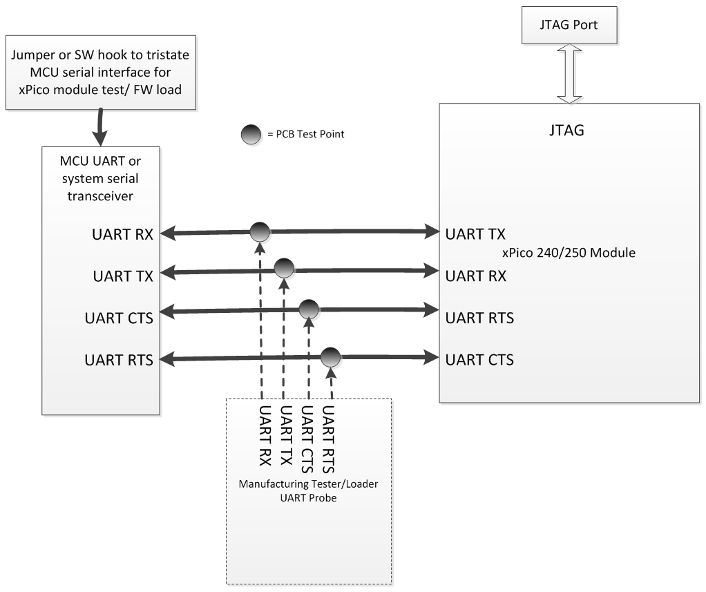
Lantronix recommends adding test points for the serial port to assist with manufacturing test loading of Secure Bit and the OEM Public Keys for SecureBoot. The current implementation requires this data be loaded via the serial interface. It is recommended to include an option to tristate other devices connected to the serial port line while the manufacturing test loading is in progress. An example of the recommended manufacturing test point is shown in the figure below.
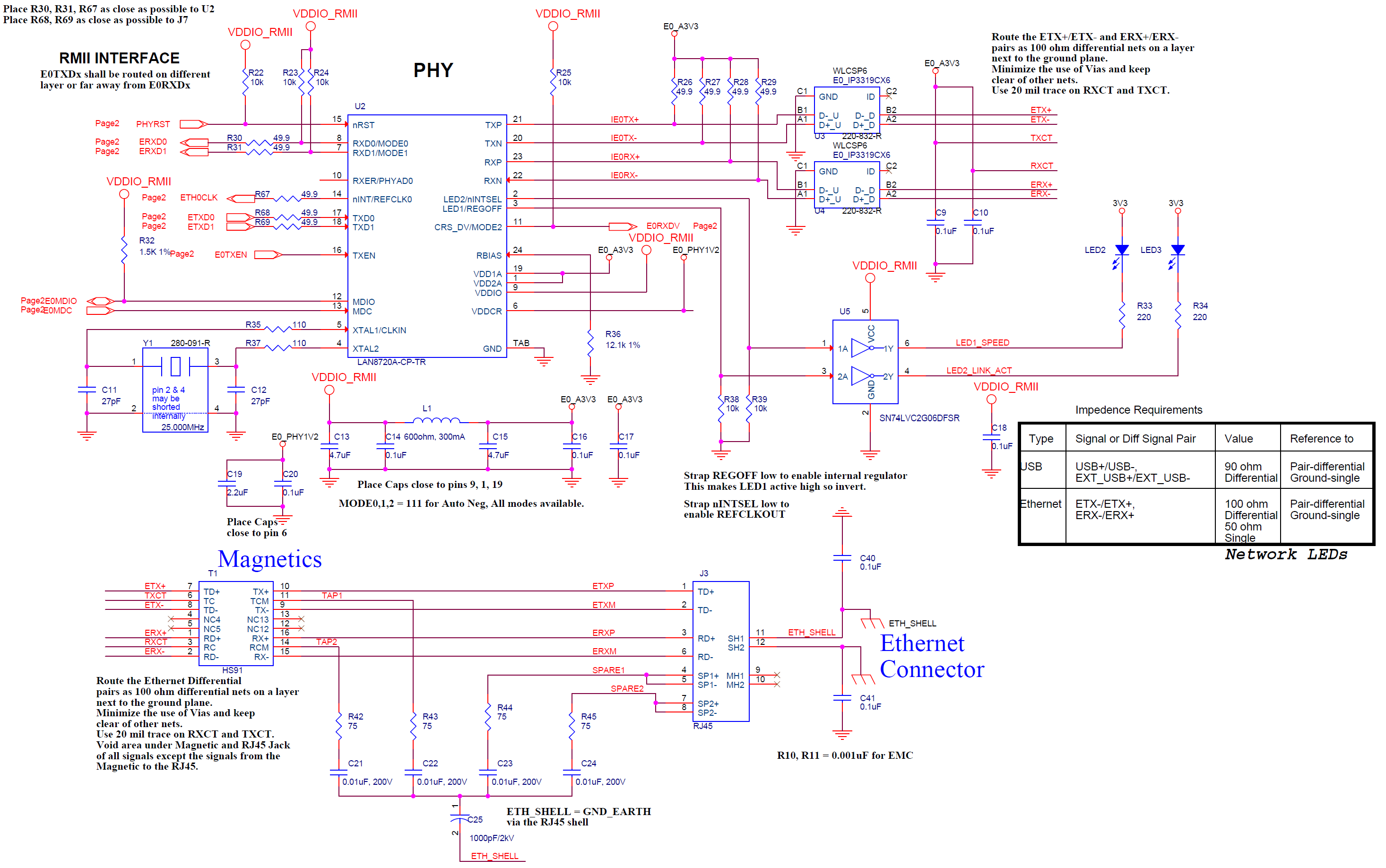
Ethernet Interface
The xPico 200 gateway has an on-board 10/100 Mbps MAC. In order to connect to a standard Ethernet network an external Ethernet PHY, magnetics, and RJ45 must be connected to the module. The Lantronix evaluation platform comes with a Microchip 8720A 10/100Mbps PHY. Please see the figure below for the recommended connections to the PHY. The evaluation board schematic and PADs artwork are available in the Platform PCB Package, and can be downloaded at the Lantronix xPico 240 product page, the Lantronix xPico 250 product page, and the Lantronix xPico 270 product page.
It is recommended to follow the Microchip PHY layout guidelines for the part number, 8720A PHY. If using an RMII PHY from a different vendor please see the layout guidelines from your PHY vendor.
Note
The xPico 200 supports only RMII PHYs. MII interface PHYs are not supported. For direct PHY to PHY connections please refer to the PHY to PHY layout recommendations from your PHY vendor.
Ethernet Interface Signals
| Pin Name | Description | SMT Pin | Edge Connector Pin |
|---|---|---|---|
| RMII_TXD0 | RMII TXD0 transmit output | 23 | 73 |
| RMII_TXD1 | RMII TXD1 transmit output | 24 | 71 |
| RMII_CLK | RMII interface clock | 25 | 61 |
| RMII_TXEN | RMII transmit enable output | 27 | 67 |
| RMII_RST | RMII reset output | 28 | 70 |
| RMII_RXDV | RMII RX data valid input | 30 | 65 |
| RMII_RXD0 | RMII RXD0 receive input | 31 | 55 |
| RMII_RXD1 | RMII RXD1 receive input | 32 | 53 |
| MDC | MDIO clock | 35 | 47 |
| MDIO | MDIO data | 36 | 49 |
Ethernet Connections to an External 10/100 PHY, Magnetics, and RJ45
Ethernet Connections to an External Switch (RMII Interface)
The xPico 200 module may be connected to an external switch via a MAC to MAC connection over the RMII interface. For external switch connections, the xPico 200 module Ethernet must be configured for Switch mode instead of PHY mode. Refer to the xPico 200 Series Embedded Wi-Fi Gateway User Guide for information on Ethernet configuration settings. In addition, the RMII port on the external switch must be configured for fixed 100Mbps, full duplex. The xPico 200 module will not work with Auto Negotiation for a MAC to MAC connection to an external switch. The RMII interface signals should be connected per the table below.
| xPico 200 Signal | Ethernet Switch Signal | Notes |
|---|---|---|
| RMII_TXD0 (out) | RMII_TXD0 (in) | |
| RMII_TXD1 (out) | RMII_TXD1 (in) | |
| RMII_CLK (in) | RMII_CLK (in) | Connect the clock for both RMII interfaces to a 50Mhz Oscillator |
| RMII_TXEN (out) | RMII_TXEN (in) | |
| RMII_RST (out) | Switch reset input active low | |
| RMII_RXDV (in) | RMII_RXDV (out) | |
| RMII_RXD0 (in) | RMII_RXD0 (out) | |
| RMII_RXD1 (in) | RMII_RXD1 (out) | |
| MDIO Clock | MDIO Clock | MDIO is not used in switch mode |
| MDIO Data | MDIO Data | MDIO is not used in switch mode |
| Set Ethernet to Switch mode | Strap external switch port to fixed 100Mbps, full duplex, Auto negotiation disabled | Required configuration |
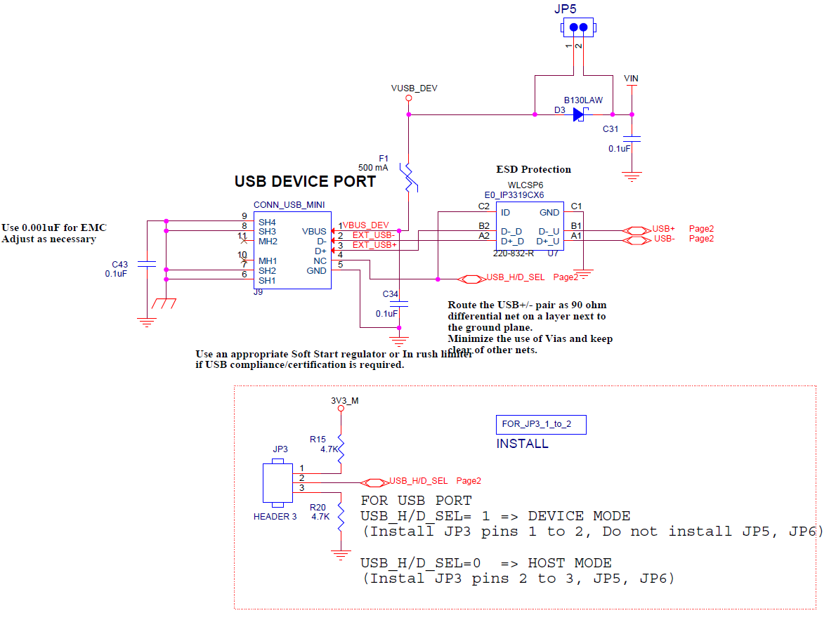
USB Device Interface
The xPico 200 gateway has one USB 2.0 device port interface for connection to an upstream USB device. The port consists of a differential pair, signals USB+ and USB-. These signals should be routed as a 90 ohm differential pair on a signal layer next to the signal ground plane. The use of vias should be minimized on these signals. The USB signals can be connected to a USB Mini Type B USB port or directly to an IC with a USB host port. If connecting to an external port that is user accessible, it is recommended to add a TVS diode array to the signal nets for ESD protection.
It is recommended that the power drawn off the USB Mini Type B connector be limited to less than 500 mA per USB power compliance requirements.
If the USB device port is unused the USB+ and USB- pins may be left disconnected.
In order to use the module in device mode the USB_H/D_SEL signal must be pulled high. The USB_H/D_SEL pin should also be connected to the ID pin of the USB connector.
USB Device Signals
| Pin Name | Description | SMT Pins |
Edge Connector Pin |
Signal Requirement |
Mini Type B USB Device Conn. Pin |
|---|---|---|---|---|---|
| USB+ | USB Device Port Positive pin | 19 | 3 | Route as 90 ohm differential pair with USB- signal | 3 |
| USB- | USB Device Port Negative pin | 20 | 5 | Route as 90 ohm differential pair with USB+ signal | 2 |
| 5V | 5V power from USB cable | Current limit to 500 mA per port | 1 | ||
| Ground | Signal Ground | Ground | Ground | Ground plane | 5 |
| USB_H/D_SEL | USB Host/Device Mode Select | 26 | 12 | Pull high for Device mode. Connect to ID pin of USB connector |
The xPico 200 gateway requires 3.3V power. If using a USB port to power the board, a 3.3V regulator must be included to supply the xPico 200 gateway. See the USB Device Interface Example for the recommended circuit.
USB Device Interface Example
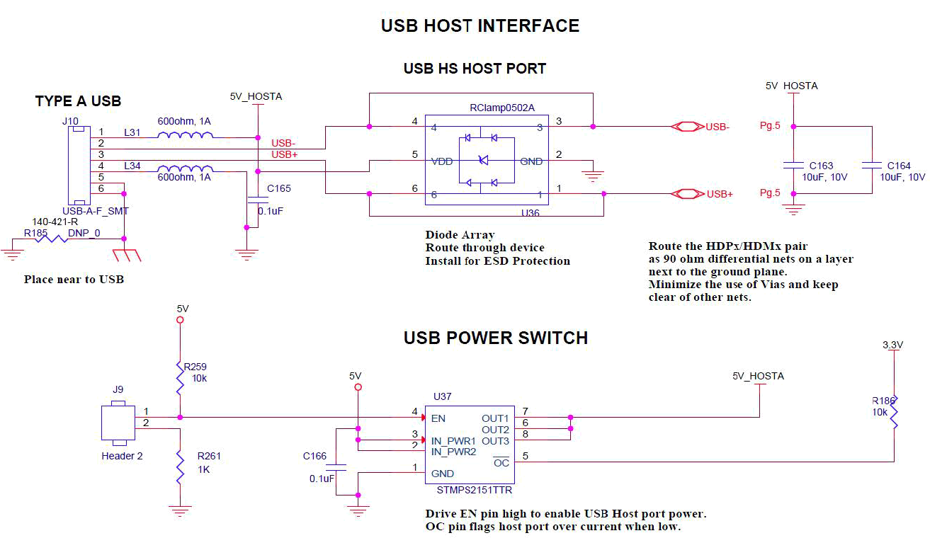
USB Host Interface
The xPico 200 gateway USB port may also be used in Host mode. The USB signals should be routed as a 90 ohm differential pair on a signal layer next to the signal ground plane. The use of vias should be minimized on these signals. The USB signals can be connected to a USB type A USB port as shown in the figure below or directly to an IC with a USB device port. If connecting to an external port that is user accessible it is recommended to add a TVS diode array to the signal nets for ESD protection. The ESD array shown in the figure is of type SEMTECH RCIamp0502A. The EDS array device features through pin routing to minimize trace impedance changes and simplify routing. The footprint for the TVS array can be added to the PCB and the part can be depopulated if it is not needed.
If connecting to an off board device that needs power, add a USB power switch to current limit the 5V power connection at the connector. USB power compliance requires that each port be limited to 500 mA maximum sustained current. If using the USB host port, the end system must take into account the amount of power consumed by the xPico 200 gateway and each USB device connected to the host port. The USB Host Interface Connections diagram below shows how to connect 5V to a USB host connector using an ST, STMPS2151 power distribution switch. The USB host port 5V power is not provided by the xPico 200 gateway.
If the USB host ports are unused their pins may be left disconnected.
In order to use the module in host mode, the USB_H/D_SEL signal must be pulled low.
Note
For host port implementations, it is recommended that the USB host port 5V power be disabled when the xPico 200 gateway is either powered OFF or in one of its low power states. To do this, the USB power distribution switch should default to OFF at board power up and when the xPico 200 gateway is in standby mode. The CP2 pin should then be configured to enable the USB power distribution switch at module boot time. This is especially important for systems planning host port connections to external self-powered USB devices as the external self-powered device may cause leakage into the module when the module is OFF or in standby. A bleed circuit may also be necessary to ensure the host port drops to 0V when the module is powered off or in standby.
USB Host Interface Signals
| Pin Name | Description | SMT Pin |
Edge Connector Pin |
Signal Requirement |
Type A USB Host Connector Pin |
|---|---|---|---|---|---|
| USB+/HHSDPB | USB HS Host Port A Positive pin | 19 | 3 | Route as 90 ohm differential pair | 3 |
| USB-/HHSDPM | USB HS Host Port A Negative pin | 20 | 5 | Route as 90 ohm differential pair | 2 |
| 5V(User-supplied) | 5V power for USB connector | Current limit to 500 mA per port | 1 | ||
| Ground | Signal Ground | Ground | Ground | Ground plane | 4 |
| USB_H/D_SEL | USB Host/Device Mode Select | 26 | 12 | Pull low for host mode. Connect to ID pin of USB connector if using A/B or Type C connector | |
| USB Host Power Enable (CP2) | Output to enable external USB power switch for host port connector (Use configurable CP2) | 12 | 48 | Pull high for Host Mode | |
| USB Host Port Over Current Flag (CP1) | Input from external USB power switch indicating the host port is over current (Use configurable pin 1) | 38 | 50 | Pull high for Host Mode |
USB Host Interface Connections
SPI Slave Interface
The xPico 200 gateway has one external SPI slave interface for connection to an external SPI master using the gSPI implementation. The signal levels on the SPI slave interface are 3.3V tolerant. This interface is shared with the SDIO interface pins. SDIO is not available in the current product release.
Note
The SPI Master interface uses different module pins than the SPI Slave interface.
SPI Slave Interface Pin Table
| Pin Name | Description | SMT Pin | Edge Connector Pin |
|---|---|---|---|
| SPI_CLK | SPI Slave Clock | 2 | 9 |
| SPI_MOSI | SPI Master Out-Slave In | 3 | 11 |
| SPI_MISO | SPI Master In-Slave Out | 4 | 13 |
| SPI_IRQ | SPI Slave Interrupt | 5 | 15 |
| SPI_CS | SPI Slave chip select | 7 | 19 |
| SDIO_MODE/SPI_SLAVE_MODE | Master/Slave
|
29 | 14 |
SPI Master Interface
The xPico 200 gateway has one external SPI master interface for connection to an external SPI slave. The signal levels on the SPI interface are 3.3V tolerant. This interface is shared with the configurable GPIO pins.
Note
The SPI Master interface uses different module pins than the SPI Slave interface.
SPI Master Interface Pin Table
| Pin Name | Description | SMT Pin | Edge Connector Pin |
|---|---|---|---|
| CP7/SPI_CLK | SPI Clock | 10 | 42 |
| CP4/SPI_MOSI | SPI Master Out-Slave In | 9 | 44 |
| CP3/SPI_MISO | SPI Master In-Slave Out | 8 | 46 |
| CP2/SPI_IRQ | SPI Interrupt | 12 | 48 |
| CP8/SPI_CS | SPI chip select | 11 | 40 |
General Purpose I/O Pins
xPico 200 gateway contains 10 pins which may be used as configurable inputs or outputs. Listed below are the configurable I/O pins. These pins are 3.3V tolerant.
| Pin Name | Description | Reset State |
SMT Pin | Edge Connector Pin |
|---|---|---|---|---|
| CP1 | Configurable I/O-USB Over Current Flag | Input | 38 | 50 |
| CP2/INT | Configurable I/O-SPI interrupt input-USB Host Port Power Enable Output | Input | 12 | 48 |
| CP3 | Configurable I/O- SPI MISO (master) | Input | 8 | 46 |
| CP4 | Configurable I/O-SPI MOSI (master) | Input | 9 | 44 |
| CP5 | Configurable I/O-I2CDATA* | Input | 15 | 58 |
| CP6 | Configurable I/O-I2CCLK* | Input | 16 | 60 |
| CP7 | Configurable I/O-SPI Clock (master) | Input | 10 | 42 |
| CP8 | Configurable I/O-SPI Chip Select (master) | Input | 11 | 40 |
| CP9 | Configurable I/O-PWM | Input | 22 | 16 |
| CP10 | Configurable I/O-PWM | Input | 37 | 62 |
| CP11 | General Purpose I/O | Input | 40 | 68 |
| CP12 | General Purpose I/O | Input | 39 | 66 |
System Pins
The xPico 240 supports four system pins: EXT_RESET#, DEFAULT#, WAKE# and SYS_LED#.
External Reset (EXT_RESET#)
xPico 200 gateways have two signals for use as reset signals. Signal EXT_RESET# is a hardware controlled input signal that will reboot the xPico 200 processor when asserted low. It is recommended to assert reset for a minimum of 50ms on systems with power ramp rates greater than 1 ms. RESET# is inactive during module power down (standby) state. Assert WAKE signal to come out of low power states prior to asserting reset. See the xPico 200 Series Embedded Wi-Fi Gateway Data Sheet at the Lantronix xPico 240 product page and the Lantronix xPico 250 product page for timing diagrams for POR, Normal mode reset, and HW WAKE.
Reset to Factory Defaults (DEFAULT#)
Signal DEFAULT# is polled by the xPico 200 software. When DEFAULT# is asserted low for six seconds, the unit will reset the system to the default manufacturing settings and reboot the unit.
Wake (WAKE#)
xPico 200 has an additional signal that can be used to wake up the unit processor when the unit is in a standby or power down state. The wake pin should be filtered as close as possible to the module. We recommend an 100 ohm resistor to a 0.1 uF cap on the signal line. The WAKE signal should be routed as short as possible to minimize noise on the signal line.
LED (SYS_LED#)
The xPico 200 gateway SYS_LED signal is intended to drive the external status LED. The System LED usually remains on. When the Default button is pressed for 6 seconds, the System LED starts blinking every second to indicate the default button can be released to complete resetting the unit to factory default. The unit reboots after release of the Default button.
xPico 200 Wi-Fi Status LED Output Signals
| Signal | SMT Pin | Edge Connector Pin | Description |
|---|---|---|---|
| SYS_LED | 33 | 6 | System status LED, active high |
xPico 200 Reset Signals
| Pin Name | Description | SMT Pin | Edge Connector Pin |
|---|---|---|---|
| EXT_RESET# | Unit hardware reset, active low. Drive low for 50 ms to reboot unit. Signal should be driven high or pulled high after reset. RESET# is inactive during module power down (standby) state. Assert WAKE signal to come out of low power states prior to asserting reset. | 41 | 52 |
| DEFAULT# | Unit reset to default, active low. Drive low for 6 seconds or longer to reset unit to default settings. May be left floating if unused. | 57 | 23 |
| WAKE | Toggle signal to WAKE from STANDBY state. WAKE signal is noise sensitive. Filter as close as possible to the module pin. | 17 | 20 |
See the xPico 200 Series Embedded Wi-Fi Gateway Data Sheet at the Lantronix xPico 240 product page and the Lantronix xPico 250 product page for timing diagrams for POR, Normal mode reset, and HW WAKE.
Strap Pins
The xPico 200 gateway has two strap pins for setting the mode of the USB and SDIO ports. These pins must be strapped high or low. The mode definitions are listed below.
xPico 200 Reset Signals
| Signal | Pin | Description | Reset State |
|---|---|---|---|
| USB_H/D_SEL | 26 | Pull high for device mode* on USB port. Pull low for host mode on USB port. Connect to ID pin of USB connector. | Input |
| SDIO_MODE/SPI_SLAVE_MODE | 29 | Pull high for master mode on SDIO port. Pull low for slave mode on SDIO port. SDIO_MODE/SPI_SLAVE_MODE has the same behavior for SPI Slave. | Input |
Module Power
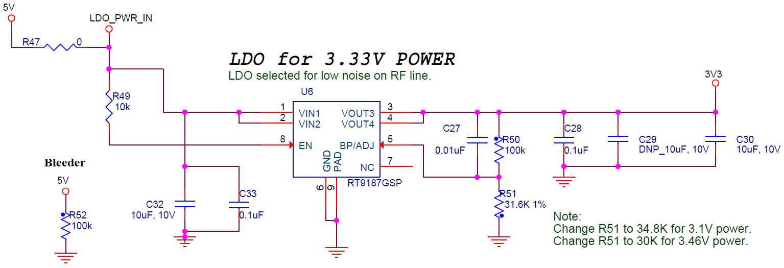
The xPico 200 requires 3.3V +/-5% power. Optimum RF performance requires a regulator with low noise and low ripple. The Lantronix evaluation board uses an LDO (Richtek RT9187) to power the xPico 200 gateway. Switching regulators may also be used, however, it is strongly recommended to use a regulator optimized for noise in RF applications. The designer should also keep the droop on the input voltage as low as possible. Droop is the difference in input voltage from the module transmitter off and transmitter on states. Module current can be as high as 600 mA with the transmitter turned on and in the low milliamps with the transmitter off and microamps in standby. The module input voltage shall not drop below the minimum specified value for ripple or droop. It is recommended to keep the module input voltage at or above a 3.3V nominal target value to account for margin due to power line variability. Refer to the xPico 200 Series Embedded Wi-Fi Gateway Data Sheet available at the Lantronix xPico 240 product page and the Lantronix xPico 250 product page for current consumption specifications.
Refer to your regulator vendor schematic and layout guidelines to minimize regulator noise, droop, and ripple for best module RF and EMC performance.
xPico Module Power
| Parameter | Symbol | Min | Typ | Max | Units |
|---|---|---|---|---|---|
| Voltage | VCC | 3.15 | 3.3 | 3.45 | V DC |
| Supply Voltage Ripple/Droop | VCC pp | ± 1% | |||
| Extended Operating Temperature | Ta | -40 | +85 | ⁰C | |
| Humidity (non-condensing, relative) | 85 | % | |||
| Power Supply ramp rate | VCC | 40 | 1000* | us |
*For slower power supply ramp rates it is recommended to assert reset for 50 ms after power reaches 3.15V.
xPico 200 External Regulator on Evaluation Platform
Hardware Certification Test Requirements
The xPico 240/250 module is pre-certified for several regions. See the xPico 200 Series Embedded Wi-Fi Gateway Data Sheet available at the Lantronix xPico 240 product page and the Lantronix xPico 250 product page for a full listing of modular certifications. If the conditions of the certifications are met, designs leveraging the xPico 240/250 modular certifications should not need to go through transmitter-specific testing for end product certifications. Full certification is normally required if using an antenna of different type and/or greater gain than used in the xPico 240/250 modular certifications. Full certification is also required for regions not covered under the certification list in the Compliance section of the xPico 200 Series Data Sheet at the Lantronix xPico 240 product page and the Lantronix xPico 250 product page.
Access to the xPico 240/250 UART is required for transmitter and receiver certification tests. Lantronix suggests adding test points to break into the module UART lines for the purpose of certification testing. An example of this connection can be seen in the UART Interface section above. The other devices on the serial port interface should have an option to tristate so they don't interfere when running the certification test mode scripts from an external PC over the UART.