Host Serial Interfaces
The XPort EDGE Embedded Ethernet Gateway provides a UART port to enable communication with a connected host microcontroller or another system.
UART
The gateway provides one UART interface for asynchronous serial communication with the microcontroller. The UART is used for device control, data communication, and debug logging.
The UART interface maps to Line 1 on the gateway. It supports asynchronous data rate up to 4 Mbps, odd/even parity, 1 and 2 stop bits, software flow control (Xon/Xoff), and hardware flow control (RTS, CTS).
Note
Flow control is required to import XML over the UART interface. Hardware flow control is recommended.
In order to set up the UART serial interface, configure the Line 1 settings.
In Web Manager, go to Line > Line 1 > Configuration.
For CLI, see Config Line Level.
For XML, see configgroup Line.
Line Configuration Settings
The following table describes the Web Manager Line configuration settings.
Links to the equivalent settings for the CLI and XML reference are listed below.
CLI settings: See Config Line Level
XML settings: See configgroup Line
| Settings | Description |
|---|---|
| Name | Name or short description for the line, if desired. By default, there is no name specified. A name that contains white space must be surrounded by quotations. |
| Interface | Serial Interface. Choices are: RS232, RS485 Half Duplex, and RS485 Full Duplex. |
| State | Operational state of the Line. Can be Enabled or Disabled. The default is an Enabled. |
| Protocol | Operational protocol for the Line. Choices are: - Command Line - MACH10 Command Interface - Modem Emulation - Monitor - Mux - None - Trouble Log - Tunnel See Line Operating Modes |
| Baud Rate | Baud Rate (bits per second) of the Line. The default is 9600. Any standard speed between 1200 and 4000000 may be selected. You may also select a custom baud rate and enter any value between 1200 and 4000000. |
| Parity | Parity of the line. The default is None. Note: Serial lines do not support the following Data Bit/Parity combinations: - 7 Data Bits with No Parity and 1 Stop Bit - 8 Data Bits with 2 Stop Bits. |
| Data Bits | Number of data bits for the Line. The default is 8. Note: Serial lines do not support the following Data Bit/Parity combinations: - 7 Data Bits with No Parity and 1 Stop Bit - 8 Data Bits with 2 Stop Bits. |
| Stop Bits | Number of stop bits for the Line. The default is 1. |
| Flow Control | Flow control for the Line. Choices: None, Hardware, Software. The default is None. Hardware flow control is only supported on Line 1. |
| Xon Char | When Flow Control is set to Software, Xon Character prefix must be set in one of three ways: Prefix decimal with a backslash (\17) Prefix hexadecimal with 0x (0x11) Prefix control character with |
| Xoff Char | When Flow Control is set to Software, Xoff Character prefix must be set in one of three ways: Prefix decimal with backslash (\19) Prefix hexadecimal with 0x (0x13) Prefix control character with |
| Gap Timer | Gap timer is the delay in milliseconds to pass from the last character received, before the driver forwards the received serial bytes. By default, the delay is four character periods at the current baud rate (minimum 1 msec). Gap Timer range is 1 to 5000 milliseconds. |
| Threshold | Number of threshold bytes which need to be received in order for the driver to forward received characters. Default value is 56 bytes. |
| Push | If defined, the driver will forward received characters after the Push sequence of characters is received. An example would be <J> |
Virtual Line Interface
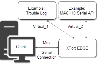
The virtual line interface sets up a virtual port on the Line 1 serial port. You can configure 2 virtual lines, 1 and 2, and define the protocol and other line settings.
Mux provides commands for sending and receiving data on multiple network connections. Mux offers simultaneous access to virtual lines and each virtual line may operate in any of the gateway's line protocols.
Use the serial terminal to open a virtual connection with Mux commands. The virtual connection establishes the configured Line protocol on the virtual port.
To send and receive data on the configured virtual line:
- Set the Line 1 protocol to Mux.
- Configure Line Virtual_1 or Virtual_2 to the desired protocol. For example, this could be tunnel or MACH10.
- Configure any other necessary settings for the protocol assigned to the virtual line. For example, configure MACH10 settings, etc.
- Use the serial terminal to open a virtual connection. The virtual connection establishes the configured Line protocol on the virtual port. See TruPort Socket for details on Mux commands to create a virtual connection.
Virtual Line Configuration Settings
The following table describes the Web Manager Line configuration settings.
Links to the equivalent settings for the CLI and XML reference are listed below.
CLI settings: See Config Line Level
XML settings: See configgroup Line
| Virtual Line Setting | Description |
|---|---|
| Name | Name or short description for the line, if desired. By default, there is no name specified. A name that contains white space must be surrounded by quotations. May contain up to 25 characters. |
| State | Operational state of the serial line. Enabled or Disabled. The default is Enabled. |
| Protocol | Operational protocol for the Line. Choices are: - Command Line - MACH10 Command Interface - Modem Emulation - Monitor - Mux - None - Trouble Log - Tunnel. See Line Operating Modes. |
| Gap Timer | Gap Timer is the delay in milliseconds to pass from the last character received, before the driver forwards the received serial bytes. By default, the delay is four character periods at the current baud rate (minimum 1 msec). Gap Timer range is 1 to 5000 milliseconds. |
| Threshold | Number of threshold bytes which need to be received in order for the driver to forward received characters. Default value is 56 bytes. |
| Push | If defined, the driver will forward received characters after the Push sequence of characters is received. An example would be <J> |
Line Printer Daemon (LPD)
Line Printer Daemon (LPD) is not included in the default firmware. To use LPD, use the SDK to create a project including the lpd module. See the Optional Features chapter of the XPort EDGE SDK User Guide for more information.
Modbus
Modbus is not included in the default firmware. To use Modbus, use the SDK to create a project including the modbus module. See the Optional Features chapter of the XPort EDGE SDK User Guide for more information.
For CLI, see Status Modbus level and Config Modbus level.
For XML, see configgroup Modbus.
Line Operating Modes
Host microcontrollers communicate with the embedded gateway through one or more of the interfaces described earlier. The gateway offers various operating modes that can be applied to these interfaces depending on the device's command and control requirements as well as the data communications requirement.
In order to bind one of the following operating modes to a particular interface, set the "line protocol" within the Line interface configuration as defined below:
TruPort Serial (Tunnel)
Serial over IP tunneling, also referred to as "serial to Ethernet," allows a serial device to communicate over a network, without being aware of the devices that establish the network connection between them.
TruPort Serial is an essential gateway application that allows a serial device connected through UART to communicate over the network transparently with one or more remote serial device or networked applications.
It is most suitable when the connected serial device software cannot be modified to add command and control logic for data communication.
By offering various knobs that control session connect, disconnect, and data framing, TruPort Serial offers a diverse set of network protocol connections and reliable data communications to enable transparent pass-through of hundreds of proprietary serial and standard fieldbus protocols across many industries.
In order to select this operating mode, set the "line protocol" for the selected interface to "Tunnel."
In Web Manager, go to Line > Line 1 > Configuration.
For CLI, see Config Line Level.
For XML, see configgroup Line.
Configuring Tunnel Connections
TruPort Serial supports the following tunnel connections:
- TCP client
- TCP server
- TCP with AES
- TCP with TLS/SSL
- UDP client
- UDP server
- UDP with AES
The following configuration options are available:
- Make a local connection
- Accept a network connection
- Configure disconnect settings
- Configure the packing mode
- View tunnel status
- View tunnel serial line status
Connection Control
Accept (Server mode)
Accept mode defines how the gateway reacts to incoming connections from a client over the network.
In Accept mode, the gateway listens (waits) for incoming connections from the network. A remote node on the network initiates the connection.
Serial data can still be received while waiting for a network connection, up to the serial buffer limit.
Connect (Client mode)
Connect mode defines how the gateway makes a client connection to a remote node on the network.
Disconnect mode
Disconnect mode specifies the optional conditions for disconnecting any connection that may be established. If any of these conditions are selected but do not occur and the network disconnects from the device, a Connect Mode connection will attempt to reconnect. However, if none of these conditions are selected, a closure from the network is perceived as a disconnect.
Data Framing Control
Data from the serial Line is queued and sent in segments, when either the timeout or byte threshold is reached or the send character is read on the serial line.
Data framing control, also called Packing mode, applies to both Accept and Connect modes.
Status and Statistics
Tunnel statistics display information about each individual connection and an aggregate status of all tunnel connections.
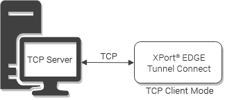
Configuring Tunnel Connect (Client Connection) in TCP Mode
This tutorial describes how to configure a TCP tunnel in Connect (Client) mode and make a connection.
You will need:
- An XPort EDGE Embedded Ethernet Gateway
- A TCP server or listener tool (e.g. BT NetTools)
Follow these steps:
-
Configure the TCP server to listen on a specific port.
-
Set Line 1 protocol to Tunnel.
-
Configure Tunnel 1 Connect. Set Mode to Always.
-
Configure Host 1. Set Address to the IP address of the TCP server and Port to the port the TCP server is listening on. Save your settings and reboot the XPort EDGE Embedded Ethernet Gateway.
-
View Tunnel 1 Status to confirm the tunnel is up and see information about active connections.
-
Type characters into serial terminals connected to the serial port of the gateway and the TCP server. The characters are echoed back on the other terminal.
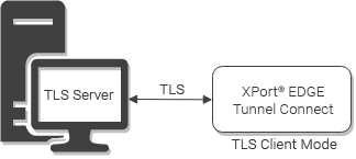
Configuring Tunnel Connect (Client Connection) in TLS Mode
You may want to create a secure connection using TLS. You'll need to first create a TLS credential. See TLS Credentials for more details. This tutorial describes how to configure a TLS tunnel in Connect (Client) mode and make a connection.
You will need:
- An XPort EDGE Embedded Ethernet Gateway with TLS credential configured
- A TLS server configured with corresponding TLS credential
Follow these steps:
-
Configure the TLS server to listen on a specific port.
-
Set Line 1 protocol to Tunnel.
-
Configure Tunnel 1 Connect. Set Mode to Always.
-
Configure Host 1. Set Address to the IP address of the TLS server and Port to the port the TLS server is listening on. Set Protocol to TLS and Credential to the name of the TLS credential.
-
Save your settings and reboot the gateway.
-
View Tunnel 1 Status to confirm the tunnel is up and see information about active connections.
-
Type characters into serial terminals connected to the serial port of the gateway and the TLS server. The characters are echoed back on the other terminal.
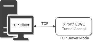
Configuring Tunnel Accept (Server Connection) in TCP Mode
This tutorial describes how to configure a TCP tunnel in Accept (Server) mode.
You will need:
- An XPort EDGE Embedded Ethernet Gateway
- A client device or terminal emulator capable of TCP connections (e.g. Tera Term, PuTTY)
Follow these steps:
-
Set Line 1 protocol to Tunnel.
-
Configure Tunnel 1 Accept. Set Mode to Always, set Local Port to the local listening port, and set Protocol to TCP. Save your settings.
-
View Tunnel 1 Status to confirm the tunnel is up. Status is Waiting.
-
Use the client device or a terminal emulator (e.g. Tera Term, PuTTY) to make a TCP/IP connection to the IP address of the desired connected interface with the listen port.
-
View Tunnel 1 Status to confirm the tunnel is up and see information about active connections.
-
Type characters into serial terminals connected to the serial port of the gateway and the TCP server. The characters are echoed back on the other terminal.
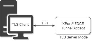
Configuring Tunnel Accept (Server Connection) in TLS Mode
As with the client connection, you can create a secure connection using TLS or TCP AES. You'll need to first create a TLS credential. See TLS Credentials for more details. This tutorial describes how to configure a TLS tunnel in Accept (Server) mode.
You will need:
- An XPort EDGE Embedded Ethernet Gateway with TLS credential configured
- A TLS-capable client configured with corresponding TLS credential
Follow these steps:
-
Set Line 1 protocol to Tunnel.
-
Configure Tunnel 1 Accept. Set Mode to Always and set Local Port to the local listening port. Set Protocol to TLS and enter the TLS credential name. Save your settings.
-
View Tunnel 1 Status to confirm the tunnel is up. Status is Waiting.
-
Use a TLS-capable client to make a TCP/IP connection to the IP address of the desired connected interface with the listen port.
-
View Tunnel 1 Status to confirm the tunnel is up and see information about active connections.
-
Type characters into serial terminals connected to the serial port of the gateway and the TLS server. The characters are echoed back on the other terminal.
Tunnel Configuration Settings
The following tables describe the Web Manager Tunnel configuration settings.
Links to the equivalent settings for the CLI and XML reference are listed before each table.
For details on how to use the CLI interface, see Configuration and Setup.
For details on how to use the XML interface, see Configuration and Setup.
Tunnel Line Settings
The tunnel line settings that are displayed are derived from the serial Line interface.
CLI settings: See Config Tunnel Line Level
XML settings: See configgroup Tunnel Line
| Settings | Description |
|---|---|
| Line | Line Settings information here is display only. Go to the serial line interface to modify the settings. |
| Protocol | Protocol information here is display only. Go to the serial line interface to modify the settings. |
| DTR | Select the DTR conditions in which Data Terminal Ready (DTR) control signal on the Serial Line is asserted. Choices: Asserted while connected (Causes DTR to be asserted whenever either a connect or an accept mode tunnel connection is active), Continuously asserted, and Unasserted. |
Tunnel Packing Settings
CLI settings: See Config Tunnel Packing Level
XML settings: See configgroup Tunnel Packing
| Settings | Description |
|---|---|
| Mode | Configure the Tunnel Packing Mode. Choices are: Disable (data not packed), Timeout (data sent after timeout occurs), and Send Character (data sent when the Send Character is read on the Serial Line). |
| Timeout | Set the timeout value, in milliseconds, after the first character is received on the serial line, before data is sent on the network. Valid range is 1 to 30000 milliseconds. Default is 1000. This configuration option becomes available when Timeout is the selected Mode. |
| Threshold | Set the threshold (byte count). If the received serial data reaches this threshold, then the data will be sent on the network. Valid range is 100 to 1450 bytes. Default is 512. This configuration option becomes available when Timeout or Send Character is the selected Mode. |
| Send Character | Enter Control Characters in any of the following forms: |
| Flush Send Character | Click to enable or disable. This configuration option becomes available when Send Character is the selected Mode. |
| Trailing Character | Enter Control Characters in any of the following forms: |
Tunnel Accept Settings
CLI settings: See Config Tunnel Accept Level
XML settings: See configgroup Tunnel Accept
| Settings | Description |
|---|---|
| Mode | Method used to start a tunnel in Accept mode. Choices: Disable: do not accept an incoming connection. Always: accept an incoming connection (default). Any Character: start waiting for an incoming connection when any character is read on the serial line. Start Character: start waiting for an incoming connection when the start character for the selected tunnel is read on the serial line. Modem Control Asserted: start when the modem control pin is asserted on the serial line. |
| Local Port | Port number for use as the network local port. The default local port for TCP on Line 1 is 10001. |
| Multiple Connections | Enabled: allow up to four incoming and four outgoing connections. Disabled: allow up to one incoming and two outgoing connections. Disabled by default. |
| Protocol | Protocol type for use with Accept Mode. The options are: TCP TCP AES TLS |
| Credential | Name of the credential associated with the selected protocol. The credential type can be AES or TLS and you configure it before setting up the accept connection. For more details, see AES Credentials or TLS Credentials. |
| Start Character | Start character that will enable the tunnel to listen for a network connection. The start character may be designated as a single printable character or as a control character. Control characters may be input in any of the following forms: This configuration option becomes available when Start Character is the selected Mode. |
| Flush Start Character | Enabled: prevents forwarding of a start character from the Line into the network. Disabled: the flush start character allows forwarding of a start character from the line into the network. This configuration option becomes available when Start Character is the selected Mode. |
| Flush Line | Whether the serial line data buffer is flushed upon a new network connection. Choices are: Enabled: serial data buffer is flushed on network connection Disabled: serial data buffer is not flushed on network connection (default) |
| Block Line | Whether Block Line is enabled for debugging purposes. Choices are: Enabled: if enabled, incoming characters from the serial line will not be forwarded to the network. Instead, they will be buffered and will eventually flow off the serial line if hardware or software flow control is configured. Disabled: this is the default setting; incoming characters from the Serial Line are sent into the network. Any buffered characters are sent first. |
| Block Network | Whether Block Network is enabled for debugging purposes. Choices are: Enabled: if enabled, incoming characters from the network will not be forwarded to the Serial Line. Instead, they will be buffered and will eventually flow off the network side. Disabled: this is the default setting; incoming characters from the network are sent on the Serial Line. Any buffered characters are sent first. |
| Password | Password can be up to 31 characters in length and must contain only alphanumeric characters and punctuation. When set, clients must send the correct password string to the unit within 30 seconds from opening network connection in order to enable data transmission. The password sent to the unit must be terminated with one of the following: 0A (Line Feed)00 (Null)0D 0A (Carriage Return/Line Feed)0D 00 (Carriage Return/Null)If Prompt for Password is set to Enabled and a password is provided, the user will be prompted for the password upon connection. |
Tunnel Connect Settings
CLI settings: See Config Tunnel Connect Level
XML settings: See configgroup Tunnel Connect
| Settings | Description |
|---|---|
| Mode | Method to start the Connect Tunnel: Disable: never started. Always: always started Any Character: started when any character is detected on the Serial Line Start Character: started when the Start Character is detected on the Serial Line. Modem Control Asserted: started when the modem control pin is asserted on the serial line. |
| Local Port | View and if desired, override the default Local Value values. Local port default values: Tunnel 1 is 10001 and Tunnel 2 is 10002. Blank the display field to restore to default random setting. |
| Host |
Lists the information related to connecting to a host. Click Edit beside a particular host to view details. Address: IP address of the remote host. If Protocol is UDP and you want to listen rather than connect, set Address to the interface to eth0. Port: the port on the remote host. Can be UDP or TCP port. If Protocol is UDP and you want to listen rather than connect, set to <None>. Default is <None>. Protocol: May be TCP, TCP AES, TLS, UDP. Default is TCP. Initial Send: string up to 32 characters. If present, the initial string is sent out before any other data when the connection is established. Click Submit to save. Up to 2 hosts can be established. |
| Connections | Select the type of connection. Sequential: connections for tunneling will begin from host 1 and proceed in sequence until a connection is accepted. Simultaneous: all hosts accepting connections will be connected. Round-Robin: the tunnel connection attempts to start with the host after whichever host had previously connected. |
| Reconnect Time | Enter the reconnection time, which specifies how long the gateway will wait in seconds before trying to reconnect to the remote host after a failed attempt or closed connection. Blank the display field to restore the default. |
| Flush Line | Select to enable or disable the flush line at the time a connection is established with the network. Enabled: buffered characters from the serial line will be discarded when a connection is established. Disabled: any characters received on the serial line will be buffered and sent after a connection is established. |
| Block Line | Select to enable or disable the block line, which is used for debugging purposes. Enabled: incoming characters from the serial line will not be forwarded to the network but will be buffered and will eventually flow off the serial line, if hardware or software flow control is configured. Disabled: incoming characters from the serial line are sent to the network. Any buffered characters are sent first. This is the “normal” setting. |
| Block Network | Select to enable or disable the block network, which is used for debugging purposes. Enabled: incoming characters from the network will not be forwarded to the serial line but will be buffered and eventually flow off the network side. Disabled: incoming characters from the network are sent on into the serial line. Any buffered characters are sent first. This is the “normal” setting. |
Tunnel Disconnect Settings
CLI settings: See Config Tunnel Disconnect Level
XML settings: See configgroup Tunnel Disconnect
| Settings | Description |
|---|---|
| Stop Character | Enter the Stop Character which when received on the Serial Line, disconnects the tunnel. The Stop Character may be designated as a single printable character or as a control character. Control characters may be input in any of the following forms: |
| Flush Stop Character | May be Enabled or Disabled. When enabled, this prevents forwarding of a stop character from the Line into the network. When disabled, this allows such forwarding. |
| Modem Control | Select to enable or disable the disconnect when modem control pin is not asserted on the serial line. |
| Timeout | Enter the number of milliseconds a tunnel may be idle before disconnection. The value of zero disables the idle timeout. |
| Flush Line | Set whether to flush the Serial Line when the Tunnel is disconnected. Choices are: - Enabled - Disabled (default) |
TruPort Socket (Mux)
TruPort Socket is a simple command and control interface that provides connected host microcontrollers access to multiple network sockets.
It is suitable for use in network co-processor mode where multiple data channels are required with fine-grained control over these data channels.
It supports serial devices connected via UART and the following socket types: UDP, TCP, AES, and TLS.
TruPort Socket accepts multiple inbound connections and initiates multiple outgoing connections and offers the ability to drop into command mode for module configuration and status.
In order to select this operating mode, set the "line protocol" for the selected interface to "Mux" and configure line settings compatible with the connected device.
In Web Manager, go to Line > Line 1 > Configuration.
For CLI, see Config Line Level.
For XML, see configgroup Line.
Using TruPort Socket (Mux)
Use the Mux commands to control connections, transfer data, and wait for events. You can also access device control through serial commands.
Mux provides machine to machine data communication, so it differs from the command line in the following ways:
- Command characters are NOT echoed.
- Each command is terminated by a single
<CR>or<LF>character unless designated otherwise. - Commands are terse.
- Responses are terse.
- No tab completion.
- No help text.
- Times out when command character(s) received but not yet ended with newline.
Usage Notes:
- Most commands comprise readable ASCII characters. The exceptions use binary-escape encoding, but these have a hex encoding alternate.
- The Mux intentionally has no configurables, as its behavior is governed entirely by the Mux commands themselves.
- Some commands offer binary-escape encoding for data transfer. To use these commands, data must be 8 bits (not 7) and flow control must be hardware (not software). If these commands cannot be used due to the line settings, data transfer can be achieved via alternate commands using hex encoding.
Steps to use Mux:
- Connect to the device through the UART serial port.
- Configure the Line 1 operating mode to Mux.
- Open a terminal or a PC running a terminal emulator to the serial line.
- Use Mux commands to connect to the device, send or receive data between the device and remote node, wait for events, and terminate the connection.
- You may also enter command line to control the device.
Mux Reference
In the following commands, <n> is a whole number such as 1, 2, or 3 that indicates the connection instance.
Controlling Connections
A “Virtual” Connection establishes the configured Line Protocol on a virtual port.
An “Accept” Connection listens on a designated port for a connection attempt from the network. More than one may be set up and used at a time. Once a connection is established, the device stops listening on the designated port; at this time the host may choose to begin accepting with the same port on another accept instance.
A “Connect” Connection initiates the attempt into the network. It must be provided with the destination port and address. More than one may be set up and used at a time.
<n>v<port>
Establish connection to a virtual port.
| Argument | Description |
|---|---|
<n> |
The instance number |
<port> |
A decimal number 1 for Virtual_1, 2 for Virtual_2, and so on designating the virtual port |
Possible responses:
| Response | Description |
|---|---|
K |
Successful |
E<string><LF> |
Error, where |
<n>a[<interface>:]<port><protocol>[,<credential>]
Begin listening for a connection from a remote node on the network.
| Argument | Description |
|---|---|
<n> |
The instance number |
<interface> |
Optional for TCP based protocols but required for UDP based protocols |
<port> |
A decimal number from 1 to 65535 representing the port to listen on |
<protocol> |
Can be “TCP”, “TCP AES”, "TLS", "UDP" |
<credential> |
The name of the credential to be used, present only if the protocol requires a credential. |
Possible Responses:
| Response | Description |
|---|---|
K |
Successfully waiting for an inbound connection; may become Active any time |
E<string><LF> |
Error, where <string> is a readable ASCII message terminated by a Line Feed. |
<n>c[<local port>]<destination>:< port>[.]<protocol>[,<credential>]
Begin connecting.
| Argument | Description |
|---|---|
<n> |
The instance number |
<local port> |
Optional; if present, it is a decimal number surrounded by square braces from 1 to 65535 representing the local port |
<destination> |
Either a hostname or an IP address |
<port> |
The optional “.” after <port> designates non-blocking connect (this requires more RAM; without the “.”, this command will not return until the connection completes or fails) |
<protocol> |
Can be “TCP”, “TCP AES”, "TLS", “UDP”, |
<credential> |
The name of the credential to be used, present only if <protocol> requires a credential. |
Possible responses:
| Response | Description |
|---|---|
K |
Waiting for an outbound connection; will reach either Active or Disabled over time. |
E<string><LF> |
Error, where <string> is a readable ASCII message terminated by a Line Feed. |
<n>h
Begin listening for HTTP.
This option works with the HTTP server, listening for a transaction directed to the URL “/mux_http”.
Possible responses:
| Response | Description |
|---|---|
K |
Successfully waiting for an inbound connection; may become Active any time |
E<string><LF> |
Error, where <string> is a readable ASCII message terminated by a Line Feed. |
<n>p
Pushes out pending send data.
Possible responses:
| Response | Description |
|---|---|
K |
Successful |
E<string><LF> |
Error, where <string> is a readable ASCII message terminated by a Line Feed. |
<n>e[<timeout>]
Ends the instance gracefully, pushing out pending send data over time but immediately dropping any receive data, where
optional <timeout> is a number representing milliseconds for timeout – if not provided, a 5000 msec timeout applies.
Possible responses:
| Response | Description |
|---|---|
K |
Successful |
T |
Timed out before all the data could be sent; instance is not ended |
E<string><LF> |
Error, where <string> is a readable ASCII message terminated by a Line Feed. |
<n>f[<timeout>]
Sends fin, pushing out pending send data over time but receive direction remains open, where
optional <timeout> is a number representing milliseconds for timeout – if not provided, a 5000 msec timeout applies.
Possible responses:
| Response | Description |
|---|---|
K |
Successful |
T |
Timed out before all the data could be sent; instance remains open for send |
E<string><LF> |
Error, where <string> is a readable ASCII message terminated by a Line Feed. |
<n>k
Kills the instance without delay.
Possible responses:
| Response | Description |
|---|---|
K |
Successful |
E<string><LF> |
Error, where <string> is a readable ASCII message terminated by a Line Feed. |
<n>
Requests current status of the instance.
Possible responses:
| Response | Description |
|---|---|
D |
Disabled |
W |
Waiting for connection establishment |
F |
Received fin, but send remains active |
R |
Sent fin, but receive remains active |
K |
Active |
<n>l<line name>
Establish connection to a line whose Protocol is None.
| Argument | Description |
|---|---|
<n> |
The instance number |
<line name> |
The name of the Line, such as 1 or CDC_ACM. |
Possible responses:
| Response | Description |
|---|---|
K |
Successful |
E<string><LF> |
Error, where |
Transferring Data
In the following commands, <bytes> is a decimal number in ASCII numeric characters.
<n>sx
Send data coded in hex.
Possible responses:
| Response | Description |
|---|---|
<bytes>K |
Okay for no more than <bytes> number of bytes. |
Now the host sends hex bytes.
The host sends a newline character to terminate. The device may terminate while the host is still sending bytes by sending E<string><LF>; otherwise the device will acknowledge the host terminating newline by sending K.
The host may decide not to send all the bytes that are allowed.
E<string><LF> - Error, where <string> is a readable ASCII message terminated by a Line Feed.
<n>sb<escape>
Send data coded in binary-escape.
Possible responses:
| Response | Description |
|---|---|
<bytes>K |
Okay for no more than <bytes> number of bytes. |
Now the host sends binary bytes.
To send a byte that matches <escape>, host sends it twice in a row.
The host sends <escape> followed by a newline to terminate. The device may terminate while the host is still sending bytes by sending E<string><LF>; otherwise the device will acknowledge the host terminating newline by sending K.
The host may decide not to send all the bytes that are allowed.
E<string><LF> - Error, where
<n>rx<bytes>[.]
Receive up to <bytes> number of bytes coded in hex.
Possible responses:
K – Accepted
The host will possibly wait indefinitely until data arrives. As data arrives, device sends to the host in hex.
Device sends <LF> after data when it terminates data mode.
Data mode terminates when:
- If “.” ends the command, last byte of an incoming packet was read.
- Number of bytes specified in command has been reached.
- Connection is dropped.
- Any single character is sent by the host.
E<string><LF> - Error, where
<n>rb<escape><bytes>[.]
Receive up to <bytes> number of bytes coded in binary-escape.
Possible responses:
K – Accepted
The host will possibly wait indefinitely until data arrives. As data arrives, device sends to the host in binary.
If the host receives <escape><escape>, it treats it as a single byte. Device sends <escape><LF> after data when it terminates data mode.
Data mode terminates when:
- If “.” ends the command, last byte of an incoming packet was read.
- Number of bytes specified in command has been reached.
- Connection is dropped.
- Any single character is sent by the host.
E<string><LF> - Error, where <string> is a readable ASCII message terminated by a Line Feed.
<n>x<encoded escape sequence>
Switch to <n> for bidirectional transfer, where <encoded escape sequence> represents an escape sequence that the host will send and look for. Alphanumeric characters do not need to be encoded.
| Argument | Description |
|---|---|
<n> |
The instance number |
<encoded escape sequence> |
The encoded escape sequence. The following encoding rules are supported: \n newline \r carriage return backslash \0 the null character \xhh hexadecimal (hh) \dmmmm delay decimal (mmmm) milliseconds (allowed only as last element); this delay (if specified) must be present after <escape sequence>. |
Possible responses:
| Response | Description |
|---|---|
K |
Successful |
E<string><LF> |
Error, where |
After this command is sent successfully, the host sends and receives bytes on <n>. The host sends <escape sequence> to pause the transfer. The device may still be sending some data, and subsequently sends <escape sequence> to acknowledge termination. The host is then back to the Mux command level. The device may terminate <instance> by sending <escape sequence>. In this situation the host must still send <escape sequence> to return to the Mux command level.
Waiting for Events
In the following command,
<event> is <n>[s | r] where s is for send ready and r is for receive ready, and <event list> is one or more concatenated events.
W<event list>
Wait for any of the listed events.
Possible responses:
K – Agreed to the event list.
Then, if any event in the list occurs, the first is returned, for example 2r<LF>. The device will wait indefinitely for any event on the list.
Host may cancel waiting by sending any single character. Device will not discard the character, so the host may send a newline for no operation or simply begin the next desired command.
Device confirms cancellation by sending a single <LF>.
E<string><LF> - Error, where <string> is a readable ASCII message terminated by a Line Feed.
Device Control
General device control is achieved via the Command Line Interface. Connections can remain open during this time.
D
Enters Command Line Interface, but with echo off. Exit from the top level returns to Mux commands.
Example
Sends hello world to a device that connects TCP to port 10001:
1a10001TCP

KW1s

K<upon connection>1s

1sb~

50KHello world!~

K1e

K
Command Line Mode
Command Line mode, also referred to as CLI or simply command mode, provides an interface through the UART port that allows you to configure and control the gateway.
Commands are structured in hierarchical levels that enable you to configure the device, read and write to the file system, view status, export and import XML configuration, and view trouble logs, help and documentation.
In order to select this operating mode, set the "line protocol" for the selected interface to "Command Line."
In Web Manager, go to Line.
For CLI, see Config Line Level.
For XML, see configgroup Line.
Using the Command Line Interface
See Configuration and Setup for details on accessing and using the command line interface.
See Command Line Reference for details on the commands and command structure.
Modem Emulation
The Modem emulation application allows you to configure the serial port on the gateway to act as a modem. A serial device that was designed for modem access can send and receive data over Local Area Network (LAN) instead of a PSTN (Public Switched Telephone Network).
In order to select this operating mode, set the "line protocol" for the selected interface to "Modem Emulation".
Modem Emulation can be run on Line 1 or Line Virtual_1 or Virtual_2.
To configure the Line operating mode:
In Web Manager, go to Line > Configuration.
For CLI, see Config Line Level.
For XML, see configgroup Line.
Configuring a Modem Emulation Connection
You can configure modem emulation mode to initiate or accept a modem connection using modem AT commands incoming from serial Line 1.
To initiate a connection
- Connect a terminal or PC running a terminal emulation program host to Line 1 of the gateway's serial port.
- Configure the terminal to the serial settings of the gateway. Use the following settings: 9600 baud, 8-bit, No parity, 1 stop bit, no flow control.
- Open a terminal emulator to the remote node and set the listen port.
- Configure the modem emulator settings to connect to the remote node. See Modem Emulation Settings.
- In the client terminal, enter the AT command to make the connection. For example, type ATD 192.0.2.0:5001 to connect to IP address 192.0.2.0 at port 5001.
- The connection is started and is in data mode. Type
AT?to view the AT command help.
See Modem Emulation AT Commands for a description of the AT commands.
To accept a connection
- Configure the serial device to dial the IP address of the gateway host.
- Configure Modem Emulation on the gateway to accept a connection attempt from the network. See Modem Emulation Settings.
- Configure the Line 1 Protocol setting on the gateway to Modem Emulation mode. See Line Configuration Settings.
- Test the connection between the client and server using client and server terminal emulators.
See Modem Emulation AT Commands for a description of the AT commands.
About Modem Emulation
For commands that can take address information (ATD, ATDT, ATDP), the destination address can be specified by entering the IP Address, or entering the IP Address and port number. The destination can also be specified with a Fully Qualified Domain Name (FQDN), and the XPort EDGE Embedded Ethernet Gateway will perform a DNS query to find the IP address of the destination address. For example, <ipaddress>:<port>. The port number cannot be entered on its own.
For ATDT and ATDP commands less than 255 characters, the XPort EDGE replaces the last segment of the IP address with the configured Connect Mode remote station address. It is possible to use the last two segments also, if they are under 255 characters. For example, if the IP address is 100.255.15.5, entering the command ATDT 16.6 results in 100.255.16.6. Use the ATDT 0 or ATDP 0 to switch to the CLI.
Once the CLI is terminated by using the CLI exit command, the XPort EDGE reverts back to modem emulation mode.
By default, the +++ characters are not passed through the connection. Turn on this capability using the modem echo pluses command.
Note
If the network connection is slow or faulty, data characters received from the Host may be backed up to the point that the Modem Emulation application is no longer reading characters from the Line, so `+++` will not be effective. A Line "break" can be used to flush the queued data, close any network connection, and return to command mode.
Note:
Modem Emulation mode is not the same as serial Tunnel mode. It does not offer the same level of capabilities and does not use the Zero-Host Load mode of operation.
Modem Emulation and Virtual Modem Emulation modes are the same.
Modem Emulation Settings
The following table describes the Web Manager Modem Emulation configuration settings.
Links to the equivalent settings for the CLI and XML reference are listed below.
CLI settings: See Config Modem Emulation
XML settings: See configgroup Modem Emulation
| Setting | Description |
|---|---|
| Listen Port | Specify a listen port to accept connections. |
| Connect Local Port | Specify a Local Port for ATD connections, as desired. This is necessary for the operation while bridging. Blank the value for <Random>. |
| Echo Pluses | Select to enable or disable echo pluses to be echoed back during “pause +++ pause” escape sequence on the serial line. |
| Echo Commands | Select to enable or disable echo commands. If enabled (ATE1), characters read on the serial line are echoed while the modem is in modem command mode. |
| Verbose Response | Select to enable or disable verbose response. If enabled (ATQ0), modem response codes are sent out on the serial line. |
| Response Type | Select either Text (ATV1) or Numeric (ATV2) representation for the modem response codes sent out on the serial line. |
| Error Unknown Commands | Select to enable or disable error unknown commands. If enabled (ATU0), ERROR is returned to the serial line for unrecognized AT commands. If disabled (ATU1), OK is returned for unrecognized AT commands. |
| Incoming Connection | Select how to handle incoming connections via the drop-down menu. Choices: Disabled (ATS0=0): refuses to answer Automatic (ATS0=1): answers immediately Manual (ATS0=2): answers via the ATA command after an incoming RING |
| Connect String | Specify a customized string to be sent with the CONNECT modem response code to the serial line, if any. May contain up to 30 characters. |
| Display Remote IP | Select to enable or disable display remote IP. If enabled, the incoming ring sent on the serial line is followed by the IP address of the caller. |
Modem Emulation AT Commands
| Command | Description |
|---|---|
| AT? | Help. Displays this table. |
| ATA | Answer incoming call request (if ATS0=2 or greater). |
| ATD | Connects to the configured Connect Mode address and port. |
| ATD | <address>:<port> Connects to the specified address and port. |
| ATD 0 | Enters the Command Line Interface (CLI); exit returns to AT commands. |
| ATDP | Same as ATD. |
| ATDT | Same as ATD. |
| ATEn | Switches echo in command mode (n=0: off, n=1: on). |
| ATH | Disconnects the network session. |
| ATI | Displays modem information. |
| ATO | Switches to data mode if connection still exists. Reverse of '+++'. |
| ATQn | Quiet mode (n=0: enable results code, n=1: disable results code.) |
| ATS0=n | Accept connection. (n=0: no, n=1: auto, n=2+: via ATA command). |
| ATUn | Accept unknown commands. (n=0: off, n=1: on). |
| ATVn | Verbose mode (n=0: numeric result codes, n=1: text result codes.) |
| ATXn | Command does nothing and returns OK status. |
| ATZ | Restore active settings from defaults. |
| AT&F | Reset saved settings in NVR to factory defaults. |
| AT&V | Display current and saved settings. |
| AT&W | Save active settings to NVR. |
| AT&Z | Restore active settings from NVR. |
| A/ | Repeat last command. |
| +++ | Switches to command mode if entered from serial port during connection. |
MACH10 Command Interface
The MACH10 Command Interface line mode provides a command interface to the MACH10 serial API. The serial API can be used to send and receive device commands from the OEM application to MACH10.
In order to select this operating mode, set the “line protocol” for the selected interface to “MACH10 Command Interface.”
MACH10 Command Interface can be run on Line 1 or Line Virtual_1 or Virtual_2.
To configure the Line operating mode:
- In the Web Manager, go to Line > Configuration. Next to Protocol, select “MACH10 Command Interface.” Click Submit.
- For CLI, see Config Line Level.
- For XML, see configgroup Line.
For the MACH10 client to work with MACH10 cloud, you also need to configure the MACH10 client's Device and Line settings. For details, see MACH10 Client.
None
This operating mode allows you to use the Web API.
In order to select this operating mode, set the "line protocol" for the selected interface to "None."
One way to use this operating mode is to set Line 1 to "Mux" and then set Line Virtual_1 or Line Virtual_2 to "None".
In Web Manager, go to Line.
For CLI, see Config Line Level.
For XML, see configgroup Line.
Trouble Log Mode
This operating mode allows you to display the trouble log in the terminal window.
In order to select this operating mode, set the "line protocol" for the selected interface to "Trouble Log."
One way to use this operating mode is to set Line 1 to "Mux" and then set Line Virtual_1 or Line Virtual_2 to "Trouble Log".
In Web Manager, go to Line > Configuration.
For CLI, see Config Line Level.
For XML, see configgroup Line.
The trouble log displays an output-only message log.
Other methods you can use to view the trouble log for the gateway include the following:
In Web Manager, enter /tlog after the IP address in the browser address bar. For example:
172.20.197.102/tlog
where 172.20.197.102 is the IP address of the gateway connected to the network.
In the CLI, run tlog from the root level.
Monitor
The Monitor feature queries and captures desired information during an XPort EDGE serial port to serial device connection. Monitoring lets you keep track of the information of connected devices while providing opportunity to make configuration changes during the monitoring.
To use the Monitor feature, you must first select the Monitor operating mode and then configure the monitoring rules and parameters.
To set the "line protocol" for the selected interface to "Monitor:"
- In Web Manager, go to Line.
- For CLI, see Config Line Level.
- For XML, see configgroup Line.
Monitor Configuration
Monitor configuration is a multi-step procedure.
In Web Manager, go to Monitor. Configure the monitoring of a connected serial device through a sequence of five pages via the Monitor Explorer Steps in Web Manager. You can also go to a specific Monitor Explorer configuration page to make specific changes. The device monitoring status can be viewed through Monitor Status page.
For CLI, see Config Monitor level.
For XML, see:
- configgroup Monitor Initialization
- configgroup Monitor Control
- configgroup Monitor Poll
- configgroup Monitor Filter
- configgroup Monitor Data
Configuring Monitor through Web Manager Explorer
Monitor configuration of a connected serial device is organized through a sequence of pages via Explorer via Web Manager. Each page is dedicated to a specific step.
Monitor Explorer Steps in Web Manager
The Web Manager user interface organizes the monitor commands in common with CLI and XML, through a series of Monitor Explorer steps.
- Step 1: Setup Initiation
- Step 2: Setup Commands
- Step 3: Define Filters
- Step 4: Pick Data
- Step 5: Confirm and submit changes
Initialization
Upon gateway power-up, the state of the external serial device is not known. Monitor will send one or more messages to bring the serial device into a known state.
- Explore your serial device and determine your strategy for bringing it to the desired starting state.
- Connect your serial device to your gateway.
- Set serial line speed, flow control, and character options through Line Configuration Settings on both the gateway and the connecting device so they are compatible. On the gateway, select Monitor under Line Protocol.
- Setup monitor initiation and monitor commands at Setup Monitor Initialization and Monitor Control. Non-printable characters are placed in the Command within square brackets. The Enter key on your PC is an ASCII Carriage Return, code
0x0d.
Polling
- Periodically your XPort EDGE will send commands to query information from your serial device.
- Explore your serial device and determine your strategy for eliciting all of the desired data with the fewest message Commands.
- Use Monitor Explorer or directly configure settings in Monitor Poll Configuration. For each message Command, determine an appropriate Timeout and possibly shorten it via a Length and/or End Character.
- Testing is rapid and simplified using Web Manager Monitor Explorer. You can see the serial device response right in your browser window.
Sample Configuration
- Use a single
showcommand to elicit the EDS2100 device status. - In Monitor Poll Configuration, set Message 1 Command to
show[0x0d]. - Testing with this, notice that the default Timeout of 100 milliseconds is too fast and Monitor sometimes polls before all the data comes out. To address this, set Timeout to 200 milliseconds for stable operation.
Note
It is possible to poll with more than one message Command. They will be sent sequentially, and you will define distinct filtering and data mining steps for each.
Filtering
The response to each poll will be sliced up according to your filter rules. The objective is to simply slice enough so you can subsequently point to the data fields you want to mine.
Note the raw data in the grey box above; it reflects what was received from the serial device. Uptime in the top right region is the target for the example.
STEP 1 - STRATEGY
Carefully examine the form of the response you receive from a particular poll. Look for cues in the response to locate your desired information. Consider if the form of the response might have variations depending on the serial device state.
STEP 2 - SETUP
Configure Monitor Filter Configuration. Rules are performed sequentially, but note that you can point each Rule to either the raw source (0) or a result of a previous rule (R.f). Each rule (R) slices the raw input into multiple fields (f), so with a dot between them (R.f) you are selecting a particular sliced result from a Rule.
STEP 3 - TEST
Testing is rapid and simplified if using Web Manager Monitor Explorer. You can see the response data sliced into pieces right in your browser window.
Sample Configuration
First slice the response into lines, point to the one containing Uptime, then slice between the caption and the time value. Setup as follows:
- Observe the Carriage Return / Line Feed sequence in the raw source.
- Rule 1 points to the raw source (Source 0), Mode = Delimiters, Delimiter 1 Binary String =
[0x0d 0x0a]. Delimiter 1 Binary String =[0x0d 0x0a]. - Observe that Uptime is in the sixth field.
- Rule 2 dices that field (Source 1.6) further, to split the caption from the value. the value.
- Observe that a colon (:) separates the caption from the data, but the data also contains colons. Data also contains colons.
- Rule 2 Mode - Delimiters, Delimiter 1 Binary String = " :" (a space followed by a colon). Use the space so it will match the transition from caption to value, but not match within the Uptime value itself.
Testing with this, confirm that the desired data is contained in a single field.
Some devices might use a variable number of lines to display status depending on the device state. If so, slicing first by lines will not consistently point to the desired data. Instead, consider a different strategy:
- Rule 1 can use Mode = Delimiters, but set the Delimiter 1 Binary String = caption.
- Its field 2 contains all of the response following the caption.
- Use Rule 2 or more to further slice 1.2 (Rule 1 field 2) in order to separate the value from anything following the caption and from the rest of the response.
Data Mining
You have already sliced the raw data multiple ways using the Filter Steps. Now select the data to be mined.
STEP 1 - STRATEGY
You can have multiple Poll messages, and different Filter Steps will generally apply to each, but some Filter Steps may be shared. Here is where you put it all together. The neat thing is that all the slicing of the raw data is virtual, so all of your Filter Rules overlay raw data from each response, but you need only care about some of them on a particular Poll message.
STEP 2 - SETUP
Use Monitor Explorer or directly configure settings in Monitor Data Configuration. Each Selector picks out a distinct data item you wish to subsequently present. The Selector Name will be presented as the caption for your data. Selector Response is a Message number; it selects the response from that Message. Selector Reference is a Rule number, dot, and a field number; it selects the desired data field.
Bottom line, you have placed a stake in the ground naming a result, identifying which poll response it comes from, and which field to pick up.
STEP 3 - TEST
Testing is rapid and simplified using Monitor Explorer. You can see the selected field contents right in your browser window.
Sample Configuration
- We'll name our result "Up time". It goes in Monitor Data Configuration under "Name"
- We only used one Poll message, so "Response" is just "1"
- Our desired data is from Rule 2, field 2. So "Reference" is "2.2"
Presenting
STEP 1 - STRATEGY
Here you consider your options for sharing the data you have mined. For human users, a Web page presentation is simplest. For machine-to-machine communication, XML might be best. Command Line could be used for either.
STEP 2 - SETUP
Your data is automatically available under Status on the Web Manager, XML, and CLI. Advanced Web customization can be done with HTML and JavaScript files dropped into the XPort EDGE.
STEP 3 - TEST
With the Web Manager, view all of your data under Monitor Status.
In the Command Line Interface (CLI), first type status to enter the status menu level, then type monitor for the Monitor menu level. From there, type show for the data.
In the XML status dump, find statusgroup name = Monitor, then statusitem name = data instance = <the name you gave your data>, and value contains the data received.
Sample Configuration
In Web Manager, select the Monitor tab at the left of the display, the select Status at the top of the display. Our "Up time" and the present value appear there.
- Visiting the Command Line Interface, we type
status, thenmonitor, thenshow. We seeUp timepresented there. - For XML we start at the root Command Line Interface, type
xml, thenxsr dump monitor. We see a statusitem name =data, instance =Up time, with value containing the present data.
Setup Monitor Initialization and Monitor Control
| Initialization Command | Description |
|---|---|
| Initial Delay <value> | Set the initial delay time in milliseconds before the monitor starts processing the initialization message. |
| Message <instance> | Edit a specific message instance; this is where a command is entered: - Command: enter the Command in binary format (printable characters or binary string). - End Character: Indicate as a single printable End Character or as a control character. Control characters may be input as <control>J, 0xA (hexadecimal) or /10 (decimal). - Length: Set the Length of the response. Maximum response length is 2048 bytes. - Timeout: Set the Timeout to receive response. Minimum timeout length is 100 milliseconds. |
Define Monitor Filters
| Filter Command | Description |
|---|---|
| Rule <instance> | Edit the specific rule instance: - Source: Indicate the input Source of the filter. For example, if the source of this filter is the second trunk of data created by filter 1, the source should be set to 1.2. A Source of 0 indicates the raw response. - Mode: Select filter Mode (All, Delimiters or Binary). - Delimiter <Number> Binary String: Enter the filter breaks input up to 8 trunks separated by binary string. Each trunk will not contain the delimiters. This field appears when Delimiter Mode is selected in Web Manager. - Start Index: Set to indicate when delimiters filter start breaking input into trunks, if the Delimiter Mode is selected. - Offset: Set the size of the first trunk of data created by the binary filter, if selected. - Length: Set the length of the second trunk of data created by the binary filter, if selected. The third trunk of data created by the binary filter will contain the rest of the input. |
Pick Monitor Data
| Pick Data Command | Description |
|---|---|
| Selector <instance> | Click the Edit link to edit a specific selector: - Name: Define the data Name as it will display. - Response: Set the Response instance source of data. Response instance corresponds to poll or control message instance. - Reference: Select the Reference output of the monitor filter. For instance, if data should select the second trunk of data created by filter 1, the reference must be set to 1.2. A Reference of 0 indicates the raw response. |
| Display | In Web Manager Explorer, select the desired live response of the monitoring configuration being established to view at any time. Filter rule options appear according to your progress establishing commands and rules. Changes in what is displayed can be useful during the configuration of monitor settings. Choose either: Responses 1-4 or Filter Rules 1-4 or All Filter Rulers |
| Data (checkbox) | In Web Manager Explorer, check the Data checkbox to enable the Display feature anytime. Uncheck checkbox to disable Display. |