Test Points & Jumper Interface
The xPico 600 EVB features jumper interface and a series of test points, which can help you to obtain the corresponding waveform of some signals.
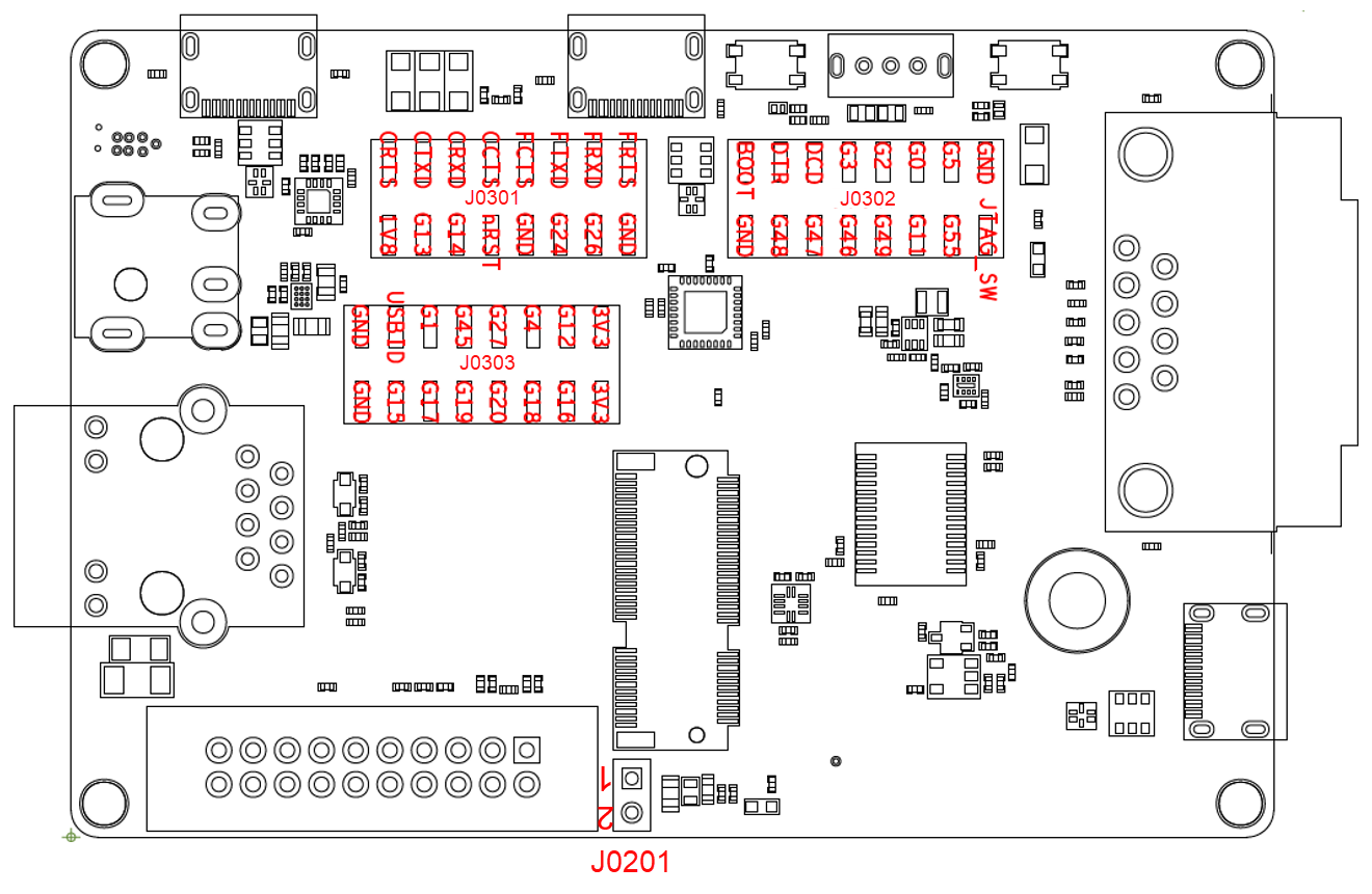
The position and pin assignment of test points J0301, J0302, J0303 and jumper interface J0201 are shown in the figure below.
Test Point Pin Definitions
J0301, J0302, J0303
| Pin Name | Description |
|---|---|
| GND | Ground |
| 3V3 | Connected to 3.3 V power supply of EVB |
| 1V8 | Connected to 1.8 V power supply of U0202 |
| CRTS | Connected to U0503 (CH343P) serial chip pins (e.g., CRTS is connected to the RTS pin of CH343P) |
| CTXD | |
| CRXD | |
| CCTS | |
| FRTS | Connected to U0501 (FT232RNQ) serial chip pins (e.g., FRTS is connected to the RTS pin of FT232RNQ) |
| FTXD | |
| FRXD | |
| FCTS | |
| nRST | Connected to RESET_N of the module |
| BOOT | Connected to BOOT of the module |
| JTAG_SW | Connected to the debug UART interface of the module and selected to JTAG mode by default |
| USBID | Connected to USB_ID of the module |
| DCD | Connected to DSD signal pin of RS232 |
| DTR | Connected to DTR signal pin of RS232 |
J0201
| Pin Name | Description |
|---|---|
| 1 | Connected to EVB power supply interface |
| 2 | Connected to VBAT of the module |