Network Interfaces
The xPico 200 series gateway contains three configurable network interfaces: Wi-Fi Client (wlan0), Wi-Fi SoftAP (ap0), and Ethernet (eth0). All three interfaces are concurrently available for communication. After applying the changes using one of the front-end management interfaces, the gateway operating system manages automatic connection management for these network interfaces without any further user or host controller intervention.
The gateway supports a number of different network topologies for the network interfaces.
LAN Uplink
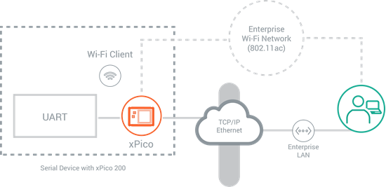
In this network configuration, xPico 200 series gateway uses the wlan0 and eth0 network interfaces as an uplink to the LAN. The connected device or gateway can communicate with different applications through any of these interfaces. The picture below provides a simplified view of this configuration:
Ethernet to Wi-Fi Bridging
When operating as a bridge, the device connects to xPico 200 series gateway via Ethernet, and it provides network access via Wi-Fi client interface (wlan0), or access to a mobile device via Wi-Fi SoftAP (ap0) interface. Bridging enables data communication along either of the following two paths (not concurrently):
- Ethernet to Wi-Fi Client
- Ethernet to SoftAP
Concurrent Wi-Fi SoftAP and Wi-Fi Client
In this network configuration, both the Wi-Fi interfaces (ap0 and wlan0) are active. Data communication occurs between the connected device or gateway and remote servers via the enterprise wireless network or with the wireless client devices associated with the SoftAP (ap0) interface.
Wi-Fi Client Only
In this network configuration, the Wi-Fi Client (wlan0) interface is the only interface enabled and communication occurs between the connected device or gateway and remote applications via the wireless network.
Wi-Fi SoftAP Only
In this configuration, the Wi-Fi Client (wlan0) is not active and communication only occurs between the connected device or gateway and the wireless client devices associated with the SoftAP (ap0) interface.
Configuring the Network Interfaces
The following sections describe each of the network interfaces:
- WLAN Client Interface (wlan0)
- SoftAP Interface (ap0)
- Ethernet Interface (eth0)
The network interfaces contain Interface and Link configuration and status settings. The Interface configuration contains properties that are related to the IP layer associated with that network interface. The Link configuration contains properties related to the data link layer (Layer 2) characteristics of that network interface. The status settings show the interface and link status on the device.
WLAN Client Interface
The WLAN client interface allows an xPico 200 series embedded gateway to connect to a WLAN network comprising of one or more Wi-Fi access points and optional backend Authentication servers. You can configure and view status of the wlan0 Interface and view the Link status.
To configure the WLAN Interface:
In Web Manager:
- Go to Network > wlan0 > Interface > Configuration.
In the CLI:
For XML:
WLAN Interface Configuration Settings
The following table describes the Web Manager WLAN Interface configuration settings.
Links to the equivalent settings for the CLI and XML reference are listed below.
CLI settings: See Config Interface level
XML settings: See configgroup Interface
| Network wlan0 Interface Settings | Description |
|---|---|
| State | Enable or disable the WLAN interface. |
| Hostname | Hostname may contain up to 63 characters. |
| Priority | Priority provides a way to determine the primary Uplink interface when both Ethernet and Wi-Fi client are enabled and operating in uplink mode. |
| MSS | Maximum Segment Size quantity in bytes. The MSS quantity applies to TCP connections on the Interface. This can be useful to avoid fragmentation over the network, which may be required because this device does not perform reassembly. |
| DHCP Client | Enable or disable the DHCP Client. |
| IP Address | IP Address. If DHCP is disabled, enter the static IP address to use for the interface. You may enter it alone (i.e., 192.168.1.1), in CIDR format (i.e., 192.168.1.1/24), or with an explicit mask (i.e., 192.168.1.1 255.255.255.0). |
| Default Gateway | Default Gateway IP address. |
| Primary DNS | Primary DNS IP address. |
| Secondary DNS | Secondary DNS IP address. |
| IPv6 State | Enable or disable IPv6 on wlan0. |
| DHCPv6 Client | Enable or disable the DHCP IPv6 Client. |
| IPv6 Auto Configuration | Enable or disable IPv6 Stateless Address Auto Configuration. |
| IPv6 Address | IPv6 Address. |
| IPv6 Default Gateway | Default Gateway for IPv6. |
| IPv6 Primary DNS | Primary DNS for IPv6. |
| IPv6 Secondary DNS | Secondary DNS for IPv6. |
Scanning for Networks
The WLAN client uses active and passive scanning for available Wi-Fi access points. Active scanning means that the client sends a probe request and waits for a probe response from an access point. On channels where active scanning is not allowed, the client uses passive scanning by listening to the beacons from the various access points without issuing active probe requests.
To scan for available networks:
In the Web Manager, use QuickConnect to scan for available networks or to find a specific network by SSID.
In the CLI, see wlan scan.
Note: All network settings require a reboot to take effect.
Enterprise Wi-Fi Security
The xPico 200 series gateway supports WPA2 Enterprise security suites and WPA/WPA2 Personal with AES/CCMP and TKIP encryption. xPico 200 series includes support for 802.1x, 802.11i and EAP authentication methods, along with PKI support and X.509 certificate management.
EAP methods provide mutual authentication algorithms to validate the wireless client with the backend authentication server and exchange key needed to access the wireless network. EAP methods supported in xPico include EAP-TLS, EAP-TTLS, EAP-PEAP, EAP-FAST, EAP-LEAP, EAP-MD5, and EAP-MSCHAPv2.
WEP
Wired Equivalent Privacy (WEP) is a simple and efficient security mode encrypting the data via the RC4 algorithm. However, WEP is acknowledged to have become more vulnerable due to advances in hacking technology.
WEP is only supported on the wlan0 interface and should only be used for associating with older access points that do not have the more secure technologies. Due to its security vulnerabilities, WEP is not recommended for use.
WPA and WPA2
Wi-Fi Protected Access (WPA) and Wi-Fi Protected Access 2 (WPA2) are security standards specified by the Wi-Fi Alliance and are derivatives of the IEEE 802.11i specification. WPA and WPA2 were developed to address the vulnerabilities found in WEP.
The xPico 200 series gateway is compliant with both WPA2 and IEEE 802.11i.
WPA2 with EAP-TLS, EAP-TTLS, or EAP-PEAP require the use of a certificate. You'll need to first create a TLS credential. See Data Communication Security (TLS) for more details.
To set up the WLAN profile to use TLS, configure the WLAN profile to EAP-TLS or EAP-TTLS and associate the TLS credential name. You'll also need a certificate for PEAP with EAP-TLS as the inner-authentication.
WLAN Network Profiles
A WLAN profile defines all of the settings necessary to establish a wireless connection with an access point (in infrastructure mode).
A maximum of four profiles can exist on the xPico 200 series embedded gateway at a time and only one profile may be connected to the WLAN network at any given time.
Creating and Configuring a WLAN Profile
To create a new WLAN profile:
- Create a profile name and save it.
- Configure the WLAN profile connection settings.
For information on the WLAN profile connection settings, see the following sections:
In Web Manager, go to WLAN Profiles.
For CLI, see Config WLAN Profile level.
For XML, see configgroup WLAN profile.
WLAN Profile Configuration Settings
The following table describes the Web Manager WLAN Profile configuration settings.
Links to the equivalent settings for the CLI and XML reference are listed below.
CLI settings: See Config WLAN Profile Level
XML settings: See configgroup WLAN Profile
| Settings | Description |
|---|---|
| Network Name (SSID) | Name of the wireless network (SSID.) |
| State | Enable or disable the profile. Enabled by default. |
| Suite | Security suite to be used for this profile. None - no authentication or encryption method will be used. WEP - wired equivalent privacy WPA - Wi-Fi protected access WPA2 - robust secure network. |
| WEP Key Size | Appropriate key size in bits. This option is available if WEP Suite is selected above. Choices: Select 40 for WEP40 and WEP64. Select 104 for WEP104 and WEP128. |
| WEP TX Key Index | One of four index listing keys for transmitting data. Reception is allowed with all four keys. For operability with some products that generate four identical keys from a passphrase, this index must be 1. This option is required if WEP Suite is selected above. |
| WEP Key 1-4 | One or more encryption keys in hexadecimal format. Enter 10 hexadecimal digits (0-9, a-f) for WEP40 and 26 for WEP104. The configured keys are not shown for security reasons. This option is required if WEP Suite is selected above. Some access point devices do not support transmit key index 2, 3 and 4 for WEP. |
| WPAx Authentication | Authentication type. The choices are PSK or 8021X. |
| WPAx IEEE 80211r | Enable to use 802.11r on this access point. If this is enabled but the access point does not support 802.11r, the connection will fail. |
| WPAx Roam over DS | Enable to exchange the first pair of frames in the roaming transition over the distribution system (network). Disable to exchange all handshake frames over the air, bypassing the currently connected access point. The access point will need to support the mode selected here. |
| WPAx Key Type | Format of the security key. This configuration option becomes available only when Suite is WPA or WPA2 and WPAx Authentication is PSK. The choices are Passphrase or Hex. |
| WPAx Key | WPAx key. This configuration option is available when Suite is WPA or WPA2 and the WPAx Key Type is Hex. |
| WPAx Passphrase | Password consisting of up to 63 characters. Lantronix recommends using a passphrase of 20 characters or more for maximum security. Spaces and punctuation characters are permitted. The passphrase input is not the same as ASCII input (as used on some products.) ASCII is translated directly into hexadecimal bytes according to the ASCII table, while a possibly larger passphrase is hashed into a key and provides better security through a larger range of key values. This configuration option becomes available only when Suite is WEP, WPA or WPA2 and WPAx Authentication is PSK. |
| WPAx IEEE 8021X | The 8021X protocol. Choices are EAP-TLS, EAP-TTLS, PEAP, FAST, and LEAP. This configuration option becomes available only when WPAx Authentication is set to 8021X. |
| WPAx Username | Username for security login. This configuration option becomes available when WPAx Authentication is set to 8021X. |
| WPAx Password | Password for security login. This configuration option becomes available when WPAx IEEE 8021X is set to EAP-TTLS, PEAP, FAST, or LEAP. |
| WPAx Credentials | The TLS credential to authenticate. This configuration option becomes available when WPAx IEEE 8021X is set to EAP-TLS or EAP-TTLS. |
| WPAx PEAP ver | PEAP version to use from the drop-down menu. Choices are 0 or 1. This configuration option becomes available when WPAx IEEE 8021X is set to PEAP. |
| WPAx PEAP Option | PEAP option to use from the drop-down menu. Choices are EAP-MSCHAPV2, EAP-MD5, or EAP-TLS. This configuration option becomes available when WPAx IEEE 8021X is set to PEAP. |
| WPAx PEAP Credentials | The TLS credential to authenticate. This configuration option becomes available when WPAx IEEE 8021X is set to PEAP. |
| WPAx FAST Option | FAST option to use from the drop-down menu. Choices are MD5, MSCHAPV2, or GTC. This configuration option becomes available when WPAx IEEE 8021X is set to FAST. |
| WPAx Encryption | One or more encryption types. Encryption types are listed with the stronger listed first. At least one selection will have to match the Access Points intended to connect with: CCMP - Uses AES as basis and is the strongest encryption option. TKIP - Uses WEP as the basis, but adds extra checks and variations for added protection. This configuration option becomes available only when Suite is WPA or WPA2. |
| TX Power Maximum | Maximum transmission output power in dBm. The range is 1-17 dBm. |
| Power Management | Radio power management reduces the overall power consumption of the xPico 200 series module, but can increase latency. Choices: Enabled - Allows the module to turn off the receiver when it is idling. Disabled - Keeps the receiver on at all times. |
| PM Interval | Number of beacons (100 msec interval) between 1 and 5. The above-mentioned latency can be up to this number “X” 100 msec. This field is available for configuration when power management is enabled. |
Connecting to WLAN Networks
There are a number of ways to connect to a Wi-Fi access point:
- Use QuickConnect using the Web Manager to scan for and connect to a Wi-Fi access point. Provide the security passphrase.
- Create and configure a WLAN profile. The gateway will attempt to connect to the configured WLAN profiles automatically on reboot. Provide the SSID and security passphrase.
For information on the supported security suites, see Enterprise Wi-Fi Security below.
Radio
The wlan0 and softap0 interfaces use the same radio and antennas. The xPico gateway can operate in concurrent AP and client mode. When the wlan0 interface has not associated with the Wi-Fi network, the ap0 interface will operate on the channel it is configured for.
Once the Wi-Fi Client interface connects, the ap0 interface switches its operation to the channel that the wlan0 interface is using.
To configure the radio and antenna settings, as well as roaming settings:
In Web Manager, go to Radio > Configuration.
In CLI, see Config Radio level.
In XML, see configgroup radio.
Radio Configuration Settings
The following table describes the Web Manager Radio configuration settings.
Links to the equivalent settings for the CLI and XML reference are listed below.
CLI settings: See Config Radio Level
XML settings: See configgroup Radio
| Radio Settings | Description |
|---|---|
| Mode | Radio mode. Choices are: Enabled - allows the Radio to operate Disabled - holds the Radio in low power Triggered - waits for CPM Role Radio Trigger to become active. Then the Radio stays up indefinitely. |
| Antenna Selection (xPico 240 only) | Antenna. Choices are: Auto - allows the Radio to select the best antenna at any time. 1 - forces the Radio to use only antenna 1. 2 - forces the Radio to use only antenna 2. |
| Keep Alive | Enabled or Disabled. Enabling this setting causes the wlan client to send a null-function data frame once per second to keep the link up. |
| Max Volley Delay | Max Volley Delay in either seconds or minutes (e.g., “40 seconds” or “1 minute”). While wlan0 is disconnected, it scans in turn for each WLAN profile. One scan per profile comprises a volley. The intervolley delay is doubled after failure to join, subject to the Max Volley Delay. Short delay will compromise ap0 performance; ap0 cannot communicate while the radio is scanning. |
| State | Enable or disable Roaming. |
| Scan Period | Scan Period in either seconds or minutes (e.g., “40 seconds” or “1 minute”). The scan period is the time between scans looking for a roaming candidate. |
| Band 2.4 GHz Trigger Delta | Band 2.4 GHz Trigger Delta value in dBm. A device with an RSSI Trigger Delta higher than the current access point is a roaming candidate. The default of 5 dBm is recommended. |
| Band 2.4 GHz RSSI Floor | Band 2.4 GHz RSSI Floor value. When the signal drops below the RSSI Floor, the radio attempts to roam. The default of -65 dBm is recommended. |
| Band 5 GHz Trigger Delta | Band 5 GHz Trigger Delta value. A device with an RSSI Trigger Delta higher than the current access point is a roaming candidate. The default of 5 dBm is recommended. |
| Band 5 GHz RSSI Floor | Band 5 GHz RSSI Floor value. When the signal drops below the RSSI Floor, the radio attempts to roam. The default of -65 dBm is recommended. |
| RSSI Floor | When scanning, any signal below the RSSI Floor is omitted. The default of -100 dBm is recommended. |
| Minimum | This setting is only available when Mode is set to Initial Delay. This is the minimum amount of delay after power on before a device will communicate with the xPico 200 series gateway. Each device is given a random delay between the Minimum and Maximum. |
| Maximum | This setting is only available when Mode is set to Initial Delay. This is the maximum amount of delay after power on before a device will communicate with the xPico 200 series gateway. Each device is given a random delay between the Minimum and Maximum. |
Wi-Fi Roaming
xPico 200 series gateways offer the ability to roam between multiple access points within the Extended Service Set Identification (ESSID) with the same network name.
The gateway software continuously tracks the signal strength of nearby access points and prevents any disruption in the wireless connection by pro-actively managing a smooth, automatic transition to the access point with the strongest signal. This provides enhanced mobility within a building or warehouse and ensures uninterrupted connectivity to the wireless network without degrading the application performance.
Based on the desired application performance with respect to latency and throughput, xPico 200 series gateway provides multiple knobs to tune the roaming configuration.
In Web Manager, to enable, disable or configure the roaming settings, go to Radio > Configuration.
Configuration changes to Radio settings require a reboot to take effect.
For CLI, see Config Radio Level
For XML, see configroup Radio.
WLAN Power Management
For battery-powered devices, you may want to reduce the power consumption by enabling the radio sleep mechanism. The xPico 200 series embedded gateway supports the 802.11 power save mode implemented in the radio.
Enabling the WLAN power management feature instructs the radio to sleep for a certain period, and then wake and listen to AP beacons. The sleep period is defined by the PM Interval setting, which is the number of beacons that the wireless station will sleep for before waking.
To enable and configure WLAN power management:
In Web Manager, go to WLAN Profiles. Select the profile that you want to edit and find the "Power Management" and "PM Interval" settings under Advanced.
In CLI, see Config WLAN Profile Advanced Level.
In XML, see configgroup WLAN Profile
Transmit Power Control
Transmit power control allows you to reduce the power of a radio transmitter to the minimum necessary level to maintain a link with quality. Configuring the transmit power control allows you to extend battery life and/or avoid interference with other nearby devices.
To set the WLAN transmit power, configure the WLAN Profiles "Advanced TX Power Maximum" level.
- In Web Manager, go to WLAN Profiles. Select the profile that you want to edit and find the "TX Power Maximum" setting under Advanced. For details about the WLAN Profile Advanced settings, see WLAN Profile Configuration Settings.
- In CLI, see Config WLAN Profile Advanced Level.
- In XML, see configgroup WLAN Profile.
SoftAP
The SoftAP interface on the gateway enables a Wi-Fi client on a mobile device or PC to connect with the gateway. SoftAP supports up to 5 WLAN clients.
Note: All network settings require a reboot to take effect.
Configuring the ap0 Interface
To configure the ap0 Interface:
In Web Manager, go to Network > ap0 > Interface > Configuration.
In the CLI, see Config Interface level.
For XML, see configgroup Interface.
Access Point ap0 Interface Configuration Settings
The following table describes the Web Manager Network ap0 interface configuration settings.
Links to the equivalent settings for the CLI and XML reference are listed below.
CLI settings: See Config Interface Level
XML settings: See configgroup interface
| Access Point ap0 Interface Settings | Description |
|---|---|
| State | Enable or disable the SoftAP State. When ap0 is enabled, the DHCP server will assign IP addresses to the SoftAP clients. A DHCP lease lasts for a day. If the IP network is managed manually, a static IP can be used outside the range of the DHCP address pool. |
| IP Address | IP Address. If not using the DHCP capabilities of the device, enter the static IP address to use for the interface. It may exist within the DHCP IP Address Range. You may enter it in one of the following ways: Alone (i.e., 192.168.1.1) CIDR format (i.e., 192.168.1.1/24) With an explicit mask (i.e., 192.168.1.1 255.255.255.0) |
| MSS | Maximum Segment Size (MSS) quantity in bytes. The MSS quantity applies to TCP connections on the interface. This can be useful to avoid fragmentation over the network, which may be required because this device does not perform reassembly. |
| Start | This is the lowest IP address the DHCP server will assign. It must exist within the ap0 subnet, be lower than or equal to the End IP address, and not be 0. |
| End | This is the highest IP address the DHCP server will assign. It must exist within the ap0 subnet, be higher than or equal to the Start IP address, and be one less than the maximum in that subnet. |
ap0 Link Setup
The ap0 Link settings correlate to the Access Point in the device. After making changes, you must re-establish any connections to the Access Point.
To configure the ap0 Link settings:
In Web Manager go to Network > ap0 > Link > Configuration.
In CLI, see Config Access Point Level
In XML, see configgroup access point
Network ap0 Link Configuration Settings
The following table describes the Web Manager access point link configuration settings.
Links to the equivalent settings for the CLI and XML reference are listed below.
CLI settings: See Config Access Point Level
XML settings: See configgroup access point
| Network ap0 Link Settings | Description |
|---|---|
| SSID | SSID is the network name of the SoftAP. SoftAP configurations take effect immediately. You may connect to the SoftAP SSID from a PC or any client using a wireless connection. After a wireless connection is successfully established, access the xPico 200 Series gateway's Web Manager from any standard web browser by entering the ap0 IP address or DNS redirect. |
| Guest | Enabled or Disabled. Disabling guest access will hide the SSID. Clients will still be able to connect to the SoftAP if they are able to connect to Hidden SSIDs. See Hidden Access Points. |
| Channel | Channel that the SoftAP interface operates on when the wlan0 (WLAN client) interface is not connected to a network. Set to <Auto> to perform a wlan scan and automatically select a channel in the configured region and band(s) with the least interference based on the channels, channel widths, and RSSI levels. This automatic scan is performed at the initial boot up, when wlan0 disassociates, or after the Auto Channel Scan Interval expires. If the wlan0 interface is connected, the ap0 interface operates on the channel used by the wlan0 connection to its access point. |
| Auto Channel Scan Interval | This setting only appears when Channel is set to <Auto>. This interval controls the duration or interval at which the device performs channel scans to determine the best available channel to operate the Soft AP interface. |
| Suite | Security Suite. Choices: None, WPA, WPA2 (highly recommended) |
| Encryption | Encryption type. CCMP uses AES as its basis and is the strongest encryption option. TKIP uses WEP as its basis, but adds extra checks and variations for added protection. |
| Passphrase | Passphrase may consist of a minimum of 8 and up to 63 characters. Space and punctuation characters are permitted. This configuration option becomes available when suites WPA or WPA2 are selected. Lantronix recommends using a passphrase of 20 characters or more for maximum security. The passphrase input is not the same as ASCII input (as used on some products.) ASCII is translated directly into hexadecimal bytes according to the ASCII table, while a possibly larger passphrase is hashed into a key and provides better security through a larger range of key values. |
| Mode | Mode. Choices are: Always Up - the SoftAP is always on. Triggered - the SoftAP waits for CPM Role "AP Trigger" to become active and then stays up according to the "uptime". Initial Trigger - the SoftAP waits for CPM Role "AP Trigger" to become active and then stays up indefinitely. Note: To disable the SoftAP state, go to the ap0 Interface settings. |
| Uptime | When Mode is set to Triggered, the uptime is the length of time in seconds, minutes, or hours that the SoftAP will remain active after it has been triggered. |
| DNS Redirect URL | URL that maps to the IP address of the interface. |
DNS Redirect
The DNS Redirect maps to the IP address of the SoftAP interface.
The default DNS redirect for xPico 200 series gateway is xpico200.lantronix.com. You can change this value to customize the URL that end users enter to access your device.
Triggered AP Mode
Triggered AP mode is a means to enable the xPico 200 series gateway's SoftAP via a hardware signal. This allows a user to have the SoftAP operating only when an external signal/button is activated. This might be useful when power consumption is a concern yet the SoftAP is needed. One potential use is device provisioning.
The configuration option for Uptime is available if the ap0 Link setting for "Mode" is set to "Triggered." When triggered, the SoftAP will remain active for the configured uptime waiting for a client to connect. If no client connects before the uptime expires, the SoftAP goes back down. If one or more clients connect, the SoftAP will remain active until the last client disconnects, at which point it will go down.
To set up triggered AP mode, you configure the CPM Role Role AP Trigger. For details about the Configuration Pin Manager, see Peripherals.
Hidden Access Points
You can hide the AP SSID so that it is not discoverable by devices via a passive scan. When the AP is hidden, the gateway will only respond to directed scans that contain the SSID.
To hide the access point, disable the Guest setting in the Access Point Link configuration.
In Web Manager, go to Network > Access Point > Link > Configuration to disable the Guest setting.
In CLI, see Config Access Point level.
In XML, see configgroup Access Point.
Ethernet
The Ethernet interface enables the Lantronix gateway to connect quickly to an Ethernet network. When the DHCP client is enabled, the network DHCP server will assign an IP address.
Note
All network settings require a reboot to take effect.
Use one of the following methods to set up the Ethernet interface:
In the Web Manager, go to Network > eth0 > Interface.
For CLI, see Config Interface Level
For XML, see configgroup interface
Network eth0 Interface Configuration Settings
The following table describes the Web Manager Network eth0 Interface Configuration settings.
Links to the equivalent settings for the CLI and XML reference are listed below.
CLI settings: See Config Interface Level
XML settings: See configgroup interface
| Network eth0 Interface Settings | Description |
|---|---|
| State | Enable or disable the Ethernet administrative state. |
| Hostname | Hostname may contain up to 63 characters. |
| Priority | Priority that the gateway will use when doing a TCP or UDP connect. |
| MSS | Maximum Segment Size quantity in bytes. The MSS quantity applies to TCP connections on the Interface. This can be useful to avoid fragmentation over the network, which may be required because this device does not perform reassembly. |
| DHCP Client | Enable or disable the DHCP Client. |
| IP Address | IP Address. If not using the DHCP capabilities of the device, enter the static IP address to use for the interface. You may enter it alone (i.e., 192.168.1.1), in CIDR format (i.e., 192.168.1.1/24), or with an explicit mask (i.e., 192.168.1.1 255.255.255.0). |
| Default Gateway | Default Gateway. |
| Primary DNS | Primary DNS. |
| Secondary DNS | Secondary DNS. |
| IPv6 State | Enable or disable IPv6 on eth0. |
| DHCPv6 Client | Enable or disable the DHCP IPv6 Client. |
| IPv6 Auto Configuration | Enable or disable IPv6 Stateless Address Auto Configuration. |
| IPv6 Address | IPv6 Address. |
| IPv6 Default Gateway | Default Gateway for IPv6. |
| IPv6 Primary DNS | Primary DNS for IPv6. |
| IPv6 Secondary DNS | Secondary DNS for IPv6. |
eth0 Link Setup
The Ethernet MAC on the module interfaces with external PHY devices via the RMII interface. The PHY has a specific address on the MDIO bus that must be specified.
The Ethernet link speed can be configured to automatic negotiation, 10 Mbps, or 100 Mbps. When not configured for automatic negotiation, the duplex mode can be set for half- or full-duplex mode.
EAP authentication can be used with the eth0 interface to provide mutual authentication algorithms to validate the client with the backend authentication server and exchange keys needed to access the network. EAP methods supported include EAP-TLS, EAP-TTLS, PEAP, and FAST. EAP-TLS, EAP-TTLS, and PEAP with EAP-TLS require the use a TLS credential. See Data Communication Security (TLS) for more details.
In the Web Manager, go to Network > eth0 > Link > Configuration to configure the link settings. After you save the changes, re-establish connections on the Ethernet link.
For the CLI, see Config Ethernet level
For XML, see configgroup Ethernet
eth0 Link Configuration Settings
The following table describes the Web Manager Network eth0 Link Configuration settings.
| Network eth0 Link Configuration Settings | Description |
|---|---|
| PHY Address | This is the address of the external Ethernet PHY device on the MDIO bus. Address 0 is default. You can configure values from 0 to 29. |
| Speed | This is the speed of the Ethernet interface. Choices: Auto, 10 Mbps, 100 Mbps. The default is Auto. The Duplex option appears if you select 10 or 100. |
| Duplex | Duplex mode of the Ethernet interface. Choices: Half or Full. The default is Half. Duplex is required only when Speed is set not set to Auto. |
| MDIO Logging | When Enabled, each access to PHY registers over the MDIO bus will be logged. Every 15 seconds, the first 32 PHY registers will dump to the log. |
| EAP Authentication | When enabled, uses EAP authentication for the interface. |
| IEEE 8021X | The 8021X protocol. Choices are EAP-TLS, EAP-TTLS, PEAP, and FAST. This configuration option becomes available only when EAP Authentication is enabled. |
| Username | Username for login. This configuration option becomes available when EAP Authentication is enabled. |
| Password | Password for login. This configuration option becomes available when IEEE 8021X is set to EAP-TTLS, PEAP, or FAST. |
| Credentials | The TLS credential to authenticate. This configuration option becomes available when IEEE 8021X is set to EAP-TLS or EAP-TTLS. |
| EAP-TTLS Option | EAP-TTLS option to use from the drop-down menu. Choices are EAP-MSCHAPV2, MSCHAPV2, MSCHAP, CHAP, PAP, or EAP-MD5. This configuration option becomes available when IEEE 8021X is set to EAP-TTLS. |
| PEAP ver | PEAP version to use from the drop-down menu. Choices are 0 or 1. This configuration option becomes available when IEEE 8021X is set to PEAP. |
| PEAP Option | PEAP option to use from the drop-down menu. Choices are EAP-MSCHAPV2, EAP-MD5, or EAP-TLS. This configuration option becomes available when IEEE 8021X is set to PEAP. |
| PEAP Credentials | The TLS credential to authenticate. This configuration option becomes available when PEAP Option is set to EAP-TLS. |
| FAST Option | FAST option to use from the drop-down menu. Choices are MD5, MSCHAPV2, or GTC. This configuration option becomes available when IEEE 8021X is set to FAST. |
Ethernet to Wi-Fi Bridge
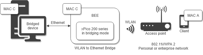
Ethernet to Wi-Fi bridging presents an Ethernet interface to host microcontrollers capable of running their own stack. Network connections to and from the bridging xPico 200 series gateway are established using the Wi-Fi or SoftAP interface, with the bridged device connected to the Ethernet interface. The bridged device can communicate with the external network via the WLAN interface or with the xPico gateway via the Ethernet interface.
When bridging is enabled and active, the MAC address of the bridged device is shared with the WLAN interface and the SoftAP interface on the xPico gateway. xPico can learn the MAC address of the bridged device or you can configure the MAC address of the bridged device.
A device on the network can communicate with the xPico gateway or the bridged device while bridging is enabled. The services of the xPico gateway versus the bridged device are determined by the ports that are open on either device. For a network device to communicate with the bridged device or xPico gateway using TCP (or another service), the network device must know the port number on the xPico gateway to send traffic to.
There are three basic bridging scenarios:
- Ethernet to Wi-Fi with static IP address
- Ethernet to Wi-Fi with dynamic IP address
- Ethernet to SoftAP
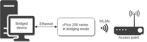
Bridging to the WLAN Interface
When bridging to the WLAN interface, you can specify a static IP address or allow DHCP to assign the IP address on the xPico gateway. If you specify a static IP address, then on the bridged device you will disable DHCP and assign a static IP address that matches the gateway. If you enable DHCP to assign the IP address on the WLAN interface, then the IP address on the bridged device will also be assigned by DHCP.
Configuring an Ethernet to WLAN Bridge
This tutorial describes how to set up a bridge for Ethernet to WLAN, with either static or dynamic IP.
You will need:
- A device with an Ethernet port to act as a bridged device. The IP address of the device can be static or dynamic
- A wireless access point
- An xPico 200 series gateway
Follow these steps:
-
Connect the Ethernet port on the bridged device to the Ethernet port on the xPico 200 series gateway.
-
Configure a WLAN profile to connect to the wireless access point. Test your xPico 200 series gateway for connectivity.
-
Configure the Bridge. Set Interface to wlan0. The wlan0 interface is assigned an AutoIP address.
-
To allow the xPico 200 series gateway to discover the MAC address of the bridged device dynamically, set Mode to Dynamic. Alternatively, set Mode to Static and set MAC Address to the MAC of the bridged device. See Bridge Configuration Settings for more information.
-
Save your settings and reboot the xPico 200 series gateway.
-
From the bridged device, ping a device on the WLAN network to confirm the bridge is up.
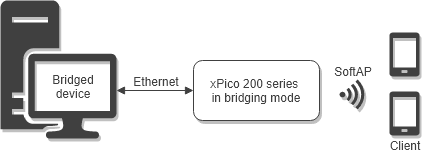
Bridging to the SoftAP Interface
An Ethernet to SoftAP (ap0) bridge establishes a restricted private network. All devices connecting to the SoftAP are assigned an IP address by the DHCP server on the ap0 interface. Up to 6 simultaneous clients can connect to Soft AP interface with the wireless client interface (wlan0) disabled. Up to 4 simultaneous clients can connect to Soft AP interface when the wireless client interface (wlan0) is active.
When bridging to the SoftAP interface, the IP address of the bridged device must be statically configured to match the IP address of the SoftAP interface of the xPico gateway. The bridged device can communicate with the xPico gateway on the Ethernet interface while bridging mode is enabled. To set this up, configure a static IP address on the xPico gateway's Ethernet Interface on the same subnet as the bridged device. If a static IP address is not configured, the eth0 interface of the xPico gateway will be assigned an AutoIP in the 169.254.x.x range. The device connected to the SoftAP can communicate if it has dual IP address capability by configuring its own second IP address to the AutoIP range.
Configuring an Ethernet to SoftAP Bridge
This tutorial describes how to set up a bridge connection for Ethernet to SoftAP.
You will need:
- A device with an Ethernet port to act as a bridged device
- A separate device with Wi-Fi (to ping from the bridged device)
- An xPico 200 series gateway, without WLAN profiles configured
Follow these steps:
-
Connect the Ethernet port on the bridged device to the Ethernet port on the xPico 200 series gateway.
-
Configure the bridged device. Assign a static IP address in the same subnet as the SoftAP (ap0) interface IP address. Note that the default IP address of the SoftAP interface is 192.168.0.1.
-
Configure the Ethernet interface (eth0). Set IP Address to an IP address in the same subnet as the bridged device, set Priority to 2, and set DHCP to Disabled.
-
Configure the SoftAP (ap0) interface. Set IP Address to an IP in the same subnet as the bridged device but different than the Ethernet interface IP address. Leave IP Address blank to use the default IP address of the SoftAP interface, 192.168.0.1.
-
Configure the Bridge. Set Interface to ap0. The ap0 interface is assigned an AutoIP address.
-
To allow xPico 200 series gateway to discover the MAC address of the bridged device dynamically, set Mode to Dynamic. Alternatively, set Mode to Static and set MAC Address to the MAC of the bridged device.
-
Save your settings and reboot the xPico 200 series gateway.
-
Use a separate device to connect to the xPico 200 series gateway via Wi-Fi. The bridge assigns the connecting device an IP address in the same subnet.
-
From the bridged device, ping the connected device to confirm the bridge is up.
Passing Multicast IP Traffic
The xPico 200 Series gateway can be configured to pass multicast IP traffic using Internet Group Management Protocol (IGMP) through the Ethernet to WLAN interface bridge or Ethernet to SoftAP bridge. The bridged client on the Ethernet interface should be configured with an IP address in the same subnet as either the network behind the external access point if using the WLAN interface or as the SoftAP if using the SoftAP interface. The IP addresses of clients using IGMP to pass multicast IP traffic must be configured in the Bridge Configuration settings.
Bridge Configuration Settings
The following table describes the Web Manager Bridge configuration settings.
Links to the equivalent settings for the CLI and XML reference are listed below.
CLI settings: See Config Bridge Level
XML settings: See configgroup Bridge
| Bridge Configuration Settings | Description |
|---|---|
| Interface | Disable the bridge interface or enable a specific interface to bridge to wlan0 or ap0. Choices: Disabled, wlan0, or ap0. Configuration for IP addressing, Static or Dynamic, must match between the bridged machine and this device. |
| Mode | Disabled - Ethernet bridging mode is disabled. Dynamic - The method to acquire the MAC Address of the bridged device. Dynamic uses the MAC address that is sent in the most recent packet by the bridged device. Static - The method to acquire the MAC Address of the bridged device. Static allows you to configure the MAC address manually. This setting is only visible when Interface is set to wlan0. |
| MAC Address | This is the MAC address used by the device. This setting is only visible when Interface is set to wlan0 and Mode is set to Static. |
| IGMP 1-6 IP Address | Up to six IP addresses can be configured to allow multicast IP traffic to pass through the Ethernet to Wi-Fi bridge using IGMP. These settings are only visible when Interface is set to wlan0 or ap0. |