Use Cases
The following examples show you how you can use the xPico 200 series gateway.
Connect to a Bluetooth SPP-enabled PC to use CLI
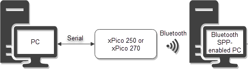
This example uses CLI over serial to configure an xPico 250 or xPico 270 to connect to a Bluetooth Classic Master SPP PC in order to use CLI over a Bluetooth connection. Because it uses CLI commands to configure the Bluetooth connection, it assumes Line 1 is already enabled and using the Command Line protocol, as is default.
Step 1 - Pair and connect to a Bluetooth Classic Master SPP PC
- Connect the xPico 200 series gateway to a PC using a serial cable. This does not need to be the same PC to which you're configuring a Bluetooth connection, but it can be.
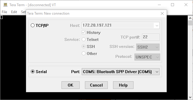
- On the PC, open a terminal such as Tera Term and connect to the device using serial. This example uses Tera Term.
- In Tera Term, type
statusto enter the status level.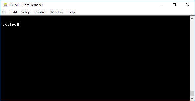
- Send
Bluetoothto enter the status Bluetooth level.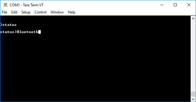
- Send
Classicto enter the status Bluetooth Classic level.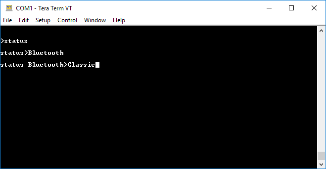
- Send
Masterto enter the status Bluetooth Classic Master level.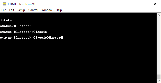
- Send
Broadcast scanto scan for compatible Bluetooth devices.
- After the results are shown, send
Connect <Device Address> SPP [passphrase]using the device address of the desired Bluetooth device from the results. The passphrase can be left blank if there is no passphrase. In this example, no passphrase is specified.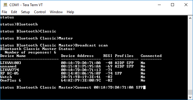
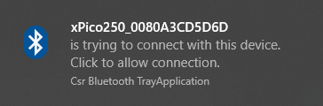
- Depending on your PC, you may need to confirm the connection from your PC.
Step 2 - Assign a Bluetooth_SPP Line
- Send the
exitcommand four times to return to the root.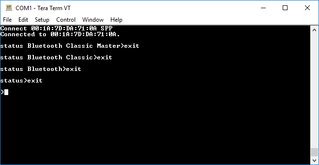
- Send
configto enter the config level.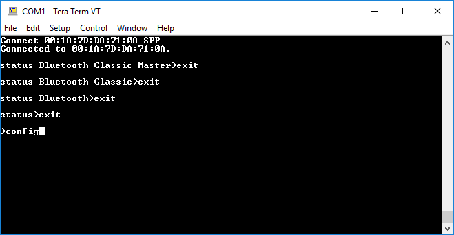
- Send
Bluetooth_SPPto enter the config Bluetooth_SPP level.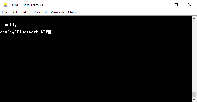
- Send
Masterto enter the config Bluetooth_SPP Master level.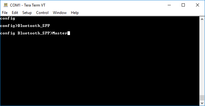
- Send
showto see a list of Bluetooth Classic Master SPP devices connected.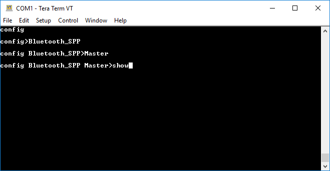
- Send
Device <Device Address>to enter the config Bluetooth_SPP Master Device level for the specified Bluetooth device.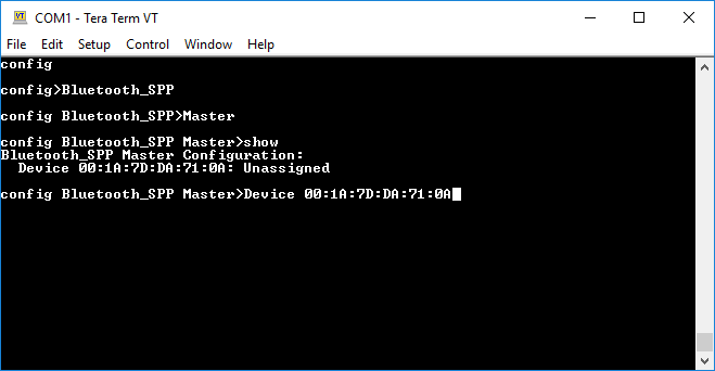
- Send
SPP Line SPP_1to assign this device to Line SPP_1.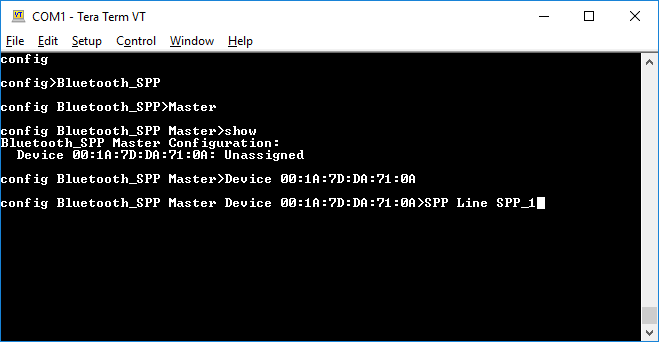
- Send
writeto write the changes.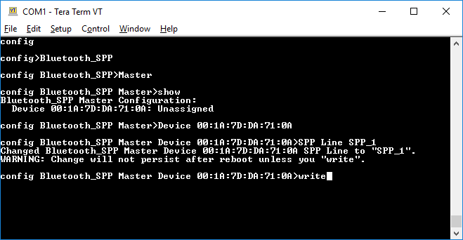
Step 3 - Configure Line SPP_1 for CLI
- Send the
exitcommand three times to return to the config level.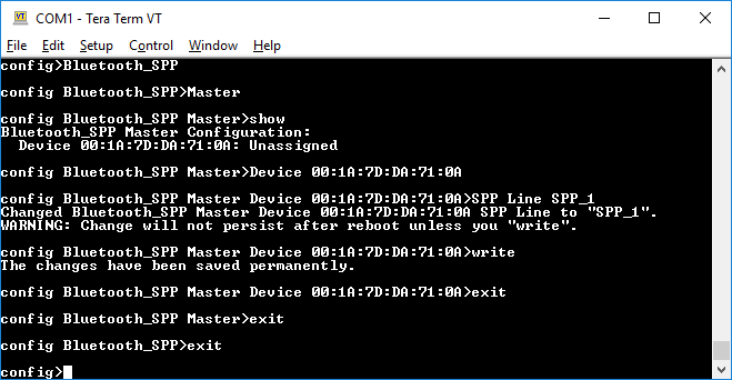
- Send
Line SPP_1to change to the config Line SPP_1 level.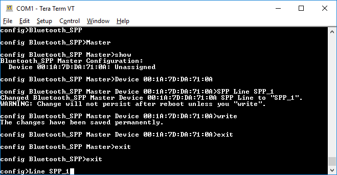
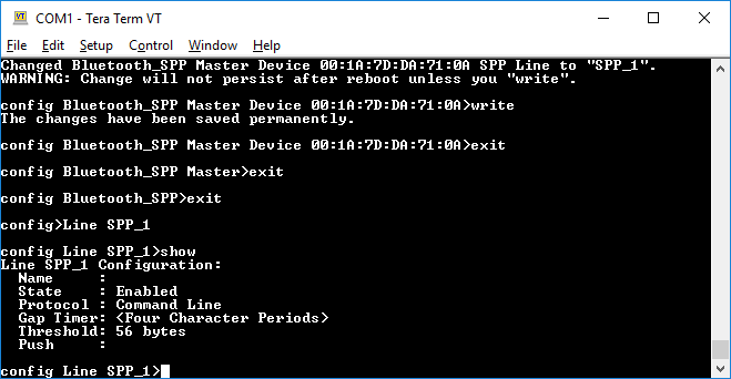
- Send
showto see the Line SPP_1 configuration.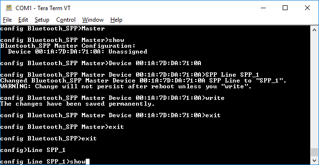
- Confirm that Line SPP_1 is enabled and using the Command Line protocol, which is default.
Step 4 - Connect to Line SPP_1 from the PC
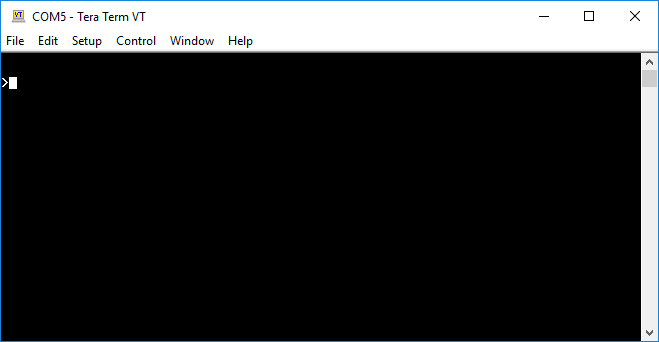
- On the Bluetooth-enabled PC, open Tera Term and connect to the device using serial and the COM port assigned to your PC's Bluetooth connection. In this example, COM5 is being used.
- You can now enter CLI commands over the Bluetooth SPP connection.
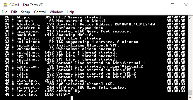
Access CLI and Trouble Log over mux, configuring via XML
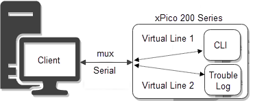
This example uses CLI to import XML configuration. The import configures Line 1 for mux, Virtual Line 1 for CLI, and Virtual Line 2 for the trouble log. It then shows how to use both those virtual lines over mux. Because it uses CLI to import the XML configuration, it assumes Line 1 is already enabled and using the Command Line protocol, as is default.
Step 1 - Import XML configuration
- Connect the xPico 200 series gateway to a PC using a serial cable.
- On the PC, open a terminal such as Tera Term and connect to the device using serial. This example uses Tera Term.
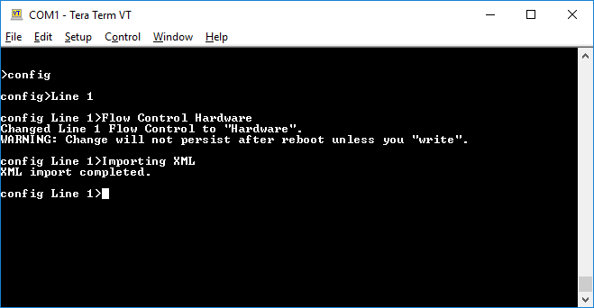
- Send
configto enter the config level. - Send
Line 1to enter the config Line 1 level. - Send
Flow Control Hardwareto set Flow Control to Hardware. Flow Control is required to import XML configuration.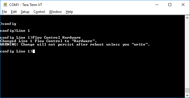
- Paste the following XML in Tera Term.
<?xml version="1.0" standalone="yes"?>
<!-- Automatically generated XML -->
<!DOCTYPE configrecord [
<!ELEMENT configrecord (configgroup+)>
<!ELEMENT configgroup (configitem+)>
<!ELEMENT configitem (value+)>
<!ELEMENT value (#PCDATA)>
<!ATTLIST configrecord version CDATA #IMPLIED>
<!ATTLIST configgroup name CDATA #IMPLIED>
<!ATTLIST configgroup instance CDATA #IMPLIED>
<!ATTLIST configitem name CDATA #IMPLIED>
<!ATTLIST configitem instance CDATA #IMPLIED>
<!ATTLIST value name CDATA #IMPLIED>
]>
<configrecord version = "0.1.0.1">
<configgroup name = "Line" instance = "1">
<configitem name = "Name">
<value></value>
</configitem>
<configitem name = "Interface">
<value>RS232</value>
</configitem>
<configitem name = "State">
<value>Enabled</value>
</configitem>
<configitem name = "Protocol">
<value>Mux</value>
</configitem>
<configitem name = "Baud Rate">
<value>9600 bits per second</value>
</configitem>
<configitem name = "Parity">
<value>None</value>
</configitem>
<configitem name = "Data Bits">
<value>8</value>
</configitem>
<configitem name = "Stop Bits">
<value>1</value>
</configitem>
<configitem name = "Flow Control">
<value>Hardware</value>
</configitem>
<configitem name = "Gap Timer">
<value><Four Character Periods></value>
</configitem>
<configitem name = "Threshold">
<value>56 bytes</value>
</configitem>
<configitem name = "Push">
<value></value>
</configitem>
</configgroup>
<configgroup name = "Line" instance = "Virtual_1">
<configitem name = "Name">
<value></value>
</configitem>
<configitem name = "State">
<value>Enabled</value>
</configitem>
<configitem name = "Protocol">
<value>Command Line</value>
</configitem>
<configitem name = "Gap Timer">
<value><Four Character Periods></value>
</configitem>
<configitem name = "Threshold">
<value>56 bytes</value>
</configitem>
<configitem name = "Push">
<value></value>
</configitem>
</configgroup>
<configgroup name = "Line" instance = "Virtual_2">
<configitem name = "Name">
<value></value>
</configitem>
<configitem name = "State">
<value>Enabled</value>
</configitem>
<configitem name = "Protocol">
<value>Trouble Log</value>
</configitem>
<configitem name = "Gap Timer">
<value><Four Character Periods></value>
</configitem>
<configitem name = "Threshold">
<value>56 bytes</value>
</configitem>
<configitem name = "Push">
<value></value>
</configitem>
</configgroup>
</configrecord>
Step 2 - Use mux to access CLI on Virtual Line 1
- Disconnect Tera Term and reconnect to the xPico 200 series gateway to access mux on Line 1.
- Type
1v1and press ENTER to connect to Virtual Line 1 as instance 1. Note that mux does not echo input characters.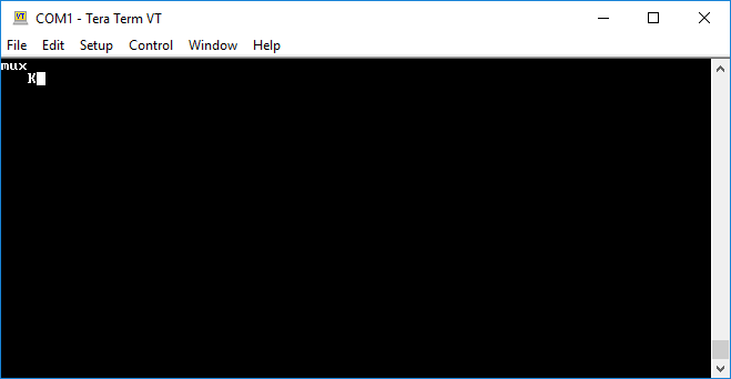
- Type
1sb~and press ENTER to prepare to send data. The~is specified as the escape character.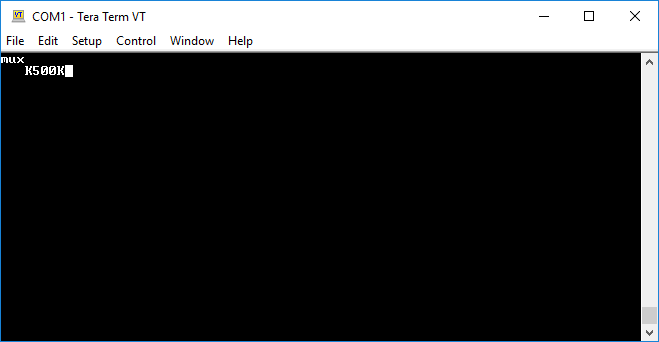
- Type
?~and press ENTER to prepare the?CLI command. The~followed by a newline terminates the data. Note that a newline is not being sent to the Virtual Line 1 because one isn't needed after the?command.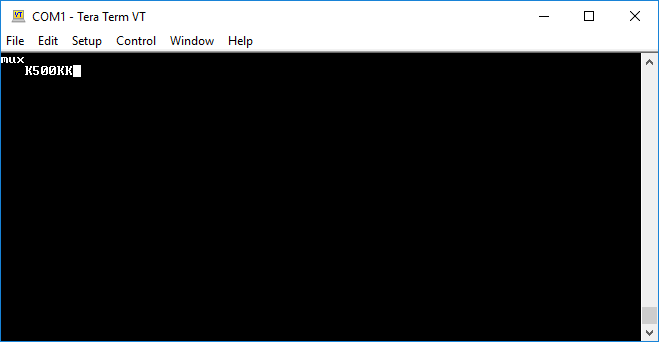
- Type
1pand press ENTER to send the prepared data.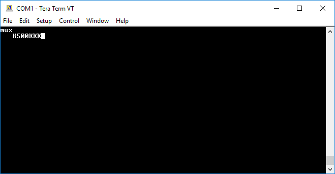
- Type
1rb~2000and press ENTER to receive data. You will see the results of the?command.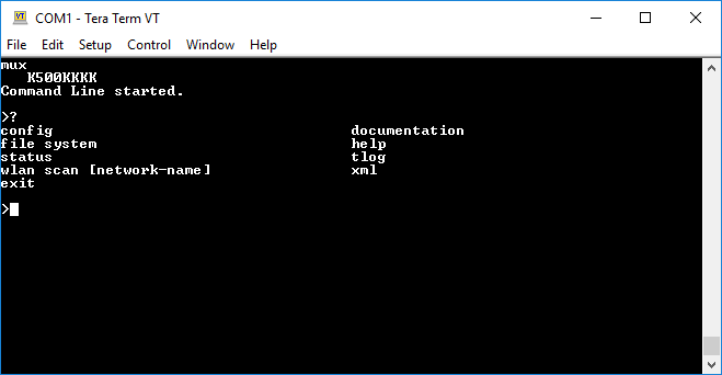
- Type
1sb~and press ENTER to prepare to send data again.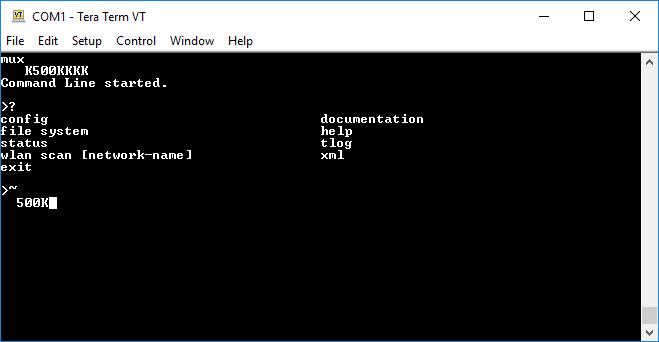
- Type
configand press ENTER to prepare theconfigcommand with a newline. Unlike the?command, theconfigcommand requires a newline. - Type
~and press ENTER to send the escape character and indicate the end of the data being prepared.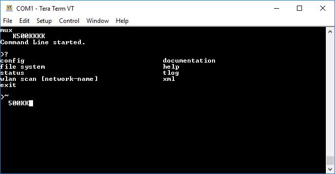
- Type
1pand press ENTER to send the prepared data.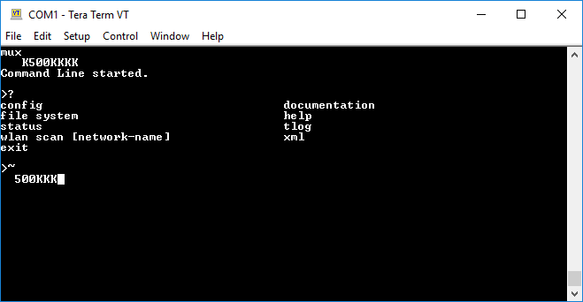
- Type
1rb~2000and press ENTER to receive data. You can repeat steps 7 through 10 to send CLI commands over mux to the Command Line on Virtual Line 1.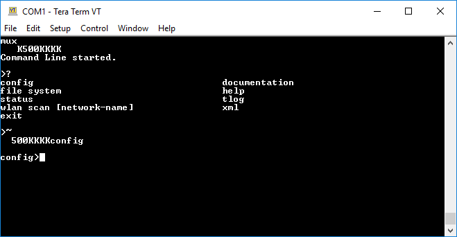
Step 3 - Use mux to access the trouble log on Virtual Line 2
- Type
2v2and press ENTER to connect to Virtual Line 2 as instance 2.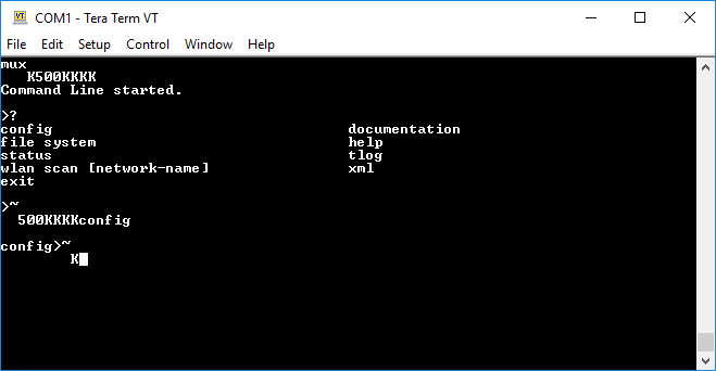
- Type
2rb~2000to receive data from the trouble log.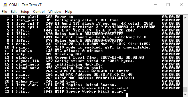
- If there is more data, repeat step 2 as necessary to receive additional data from the trouble log.