Reflow Profile Guidelines
To guarantee module soldering quality, the thickness of stencil for the module is recommended to be 0.12-0.15 mm.
The recommended peak reflow temperature should be 235–246 °C, with 246 °C as the absolute maximum reflow temperature. To avoid damage to the module caused by repeated heating, it is recommended that the module should be mounted only after reflow soldering for the other side of PCB has been completed.
The recommended reflow soldering thermal profile (lead-free reflow soldering) and related parameters are shown in the image and table below.
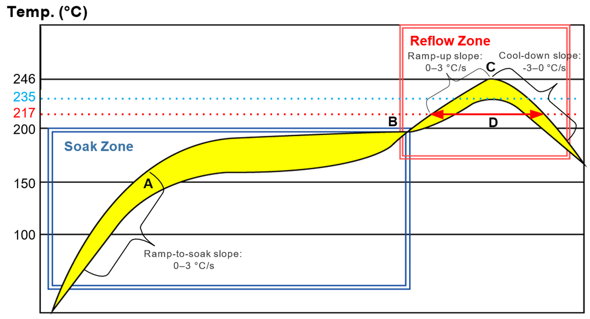
Recommended Thermal Profile Parameters
| Factor (Soak Zone) | Recommended Value |
|---|---|
| Soak Zone: | |
| Ramp-to-soak slope | 0-3 °C/s |
| Soak time (between A and B: 150 °C and 200 °C) | 70-120 s |
| Reflow Zone: | |
| Ramp-up slope | 0-3 °C/s |
| Reflow time (D: over 217 °C) | 40-70 s |
| Max. temperature | 235-246 °C/s |
| Cool-down slope | -3-0 °C/s |
| Reflow Cycle: | |
| Max. reflow cycles | 1 |
Additional Notes
- The above profile parameter requirements are for the measured temperature of solder joints. Both the hottest and coldest spots of solder joints on the PCB should meet the above requirements.
- During manufacturing and soldering, or any other processes that may contact the module directly, NEVER wipe the module’s shielding can with organic solvents, such as acetone, ethyl alcohol, isopropyl alcohol, trichloroethylene. Otherwise, the shielding may rust.
- The shielding can for the module is made of Cupro-Nickel base material. It is tested that after 12 hours’ Neutral Salt Spray test, the laser engraved label information on the shielding can is still clearly identifiable and the QR code is still readable, although white rust may be found.
- If a conformal coating is necessary for the module, do NOT use any coating material that may chemically react with the PCB or shielding cover, and prevent the coating material from flowing into the module.
- Avoid using ultrasonic technology for module cleaning since it can damage crystals inside the module.
- Avoid using materials that contain mercury (Hg), such as adhesives, for module processing, even if the materials are RoHS compliant and their mercury content is below 1000 ppm (0.1%).
- Corrosive gases may corrode the electronic components inside the module, affecting their reliability and performance, and potentially leading to a shortened service life that fails to meet the designed lifespan. Therefore, do not store or use unprotected modules in environments containing corrosive gases such as hydrogen sulfide, sulfur dioxide, chlorine, and ammonia.
- Due to the complexity of the SMT process, please contact Lantronix Technical Support in advance for any situation that you are not sure about