Antenna Interfaces
Appropriate antenna type and design should be used with matched antenna parameters according to specific application. It is required to perform a comprehensive functional test for the RF design before mass production of terminal products. The entire content of this chapter is provided for illustration only. Analysis, evaluation, and determination are still necessary when designing target products.
The xPico 600 module utilizes a dual antenna design with antenna diversity, offering two RF coaxial connectors for enhanced signal reception.
RF Coaxial Connector
Antenna Connector Specifications
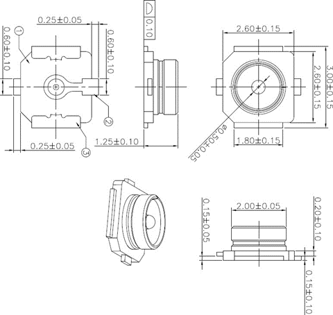
The mechanical dimensions of the receptacle mounted on the module are shown below.
Major Specifications of the RF Connector
| Item | Specification |
|---|---|
| Nominal Frequency Range | DC to 6 GHz |
| Nominal Impedance | 50 Ω |
| Temperature Rating | -40° C to +85° C |
| Voltage Standing Wave Ratio (VSWR) | Meet the requirements of: Max 1.3 (DC-3 GHz) Max 1.4 (3-6 GHz) |
Requirements for Antenna Design
| Parameter | Requirements |
|---|---|
| Frequency Range | 2.4 GHz: 2.400-2.4835 GHz 5 GHz: 5.150-5.850 GHz |
| RF Coaxial Connector | VSWR: ≤ 2 Gain: 1 dBi (Typ.) Max. Input Power: 50 W Input Impedance: 50 Ω Vertical Polarization Cable Insertion Loss: %lt; 1 dB |
RF connectors and cables by I-PEX (MHF 4L; see i-pex.com) or Hirose (W.FL Series; see hirose.com) are recommended.