System Pins
RESET_N
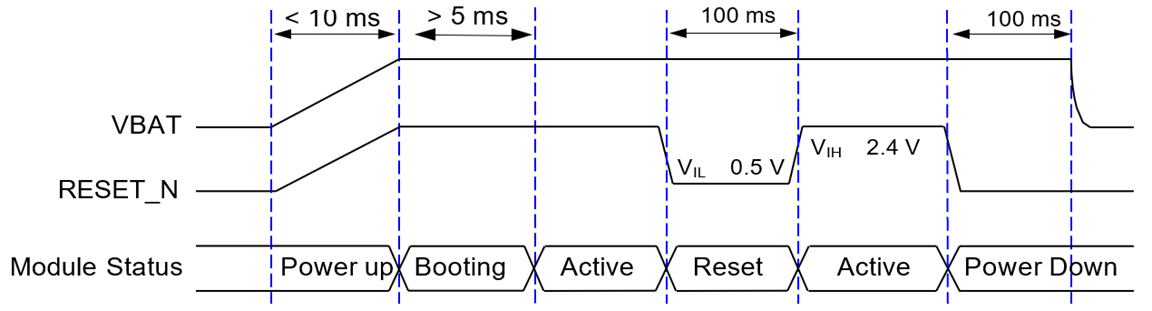
After the xPico 600 module VBAT is powered on, keep the RESET_N at high level for more than 5 ms to realize the automatic startup of the module; keep the RESET_N at low level for at least 100 ms and then release it to reset the module.
Pin Description of RESET_N
| Pin Name | LGA Pin No. | M.2 Pin No. | I/O1 | Description | Comment |
|---|---|---|---|---|---|
| RESET_N | 16 | 52 | DI | Reset the module | A test point is recommended to be reserved if unused. Active low |
The module turn-on, turn-off, and reset timing diagram is shown below.
Note
RESET_N is internally integrated with a 51 kΩ pull-up resistor to VBAT.
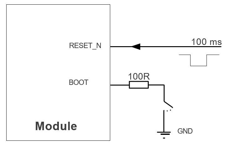
BOOT
The xPico 600 module boots from the internal Flash partition by default.
Pin Description of BOOT
| Pin Name | LGA Pin No. | M.2 Pin No. | I/O1 | Status After Reset1 | Description | Comment |
|---|---|---|---|---|---|---|
| BOOT | 61 | 42 | DI | H | Boot mode selection | 1.71-1.89 V |
-
Refer to the I/O Parameter Definitions table for an explanation of these abbreviations. ↩↩↩