USB Interfaces
The xPico 600 module provides one integrated Universal Serial Bus (USB) interface as device which complies with the USB 2.0 specification and supports high-speed (480 Mbps) mode and is backwards-compatible with full-speed (12 Mbps) mode.
Pin Description of USB Interfaces
| Pin Name | LGA Pin No. | M.2 Pin No. | I/O1 | Description | Comment |
|---|---|---|---|---|---|
| USB_DP | 29 | 3 | AIO | USB 2.0 differential data (+) | Require differential impedance of 90 Ω USB 2.0 compliant |
| USB_DM | 30 | 5 | AIO | USB 2.0 differential data (+) | Require differential impedance of 90 Ω USB 2.0 compliant |
| USB_VBUS | 31 | 64 | AIO | VBUS selection | 5 V analog power supply |
| USB_ID | 28 | 40 | AI | USB ID detect | -- |
Note
When VBAT is not supplying power, do not supply power to USB_VBUS, otherwise it may cause the module to malfunction.
The image below shows the USB interface connection between the module and the host.
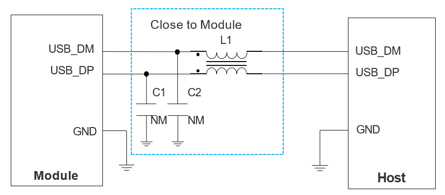
When designing the USB interface, you should follow the following principles to meet USB 2.0 specifications:
- Route the USB signal traces as differential pairs with ground on the same layer and with ground planes above and below. The differential impedance of USB 2.0 is 90 Ω ±10 %.
- Do not route signal traces under crystals, oscillators, magnetic devices, sensitive circuits/signals, such as RF circuits and analog signals, as well as noisy signals such as clock signals and DC-DC signals.
- If there is no built-in pull-down resistor inside the host, a 15 kΩ resistor should be used to pull down the USB_DP and USB_DM to the ground near the host side.
For more details about the USB 2.0 specifications, visit https://www.usb.org.
-
Refer to the I/O Parameter Definitions table for an explanation of these abbreviations. ↩